Production method for annular rubber sleeve
A production method and rubber sleeve technology, which is applied in the production field of annular rubber sleeves, can solve the problems of poor sealing performance, lower production costs, and high production costs, and achieve improved sealing performance and durability, reduced production costs, and good bonding effects Effect
- Summary
- Abstract
- Description
- Claims
- Application Information
AI Technical Summary
Problems solved by technology
Method used
Image
Examples
Embodiment 1
[0047] Such as Figure 9 Shown is the annular rubber sleeve 330 that needs to be formed in this embodiment. The annular rubber sleeve 330 has a cylindrical structure with a toothed section inside and a smooth plane outside. Specifically, such as Figure 7 As shown, the annular rubber sleeve 330 of this embodiment is spliced sequentially by a plurality of rubber sleeve pieces 300, and the bottom of the rubber sleeve piece 300 is evenly spaced with a plurality of tooth structures 310, and the tooth structure 310 of the rubber sleeve piece 300 Located inside the annular rubber sleeve 330 . Different numbers of rubber sleeves 300 are sequentially spliced to form annular rubber sleeves 330 of different diameters. Only one set of molds is needed to make rubber sleeves 300 of the same size, which can meet the requirements of different sizes of annular rubber sleeves 330 , to avoid frequent replacement of molds like the traditional round mold method, greatly reducing production ...
Embodiment 2
[0059] The production method of a kind of annular rubber sleeve of this embodiment, the basic structure is the same as that of embodiment 1, and its difference is, the annular splicing method in the S3 step in this embodiment can also adopt the following splicing method: according to the annular rubber sleeve 330 Cut the film blank 400 of the corresponding size, wind the two ends of the spliced rubber sleeve 300 into a ring structure, place the cut film blank 400 between the two ends, and place the spliced film blank 400 in the spliced Connecting rubber blocks 500 are placed in the gaps 301 at both ends of the rubber sleeve sheet 300 , and the annular rubber sleeve 330 is formed after pressing. Specifically, such as Figure 5 As shown, in this embodiment, the auxiliary forming mold 600 is placed at the bottom of the lower mold 200, and the sequentially spliced rubber sleeves 300 are placed in the avoidance cavity 610 at the bottom of the auxiliary forming mold 600, and i...
Embodiment 3
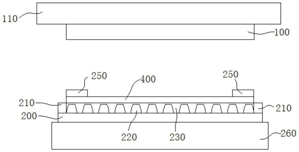
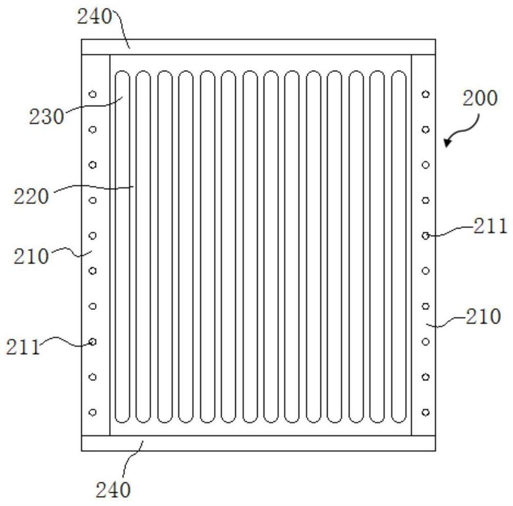
[0064] The production method of a kind of annular rubber sleeve of present embodiment, basic structure is identical with embodiment 1, further, as figure 2 As shown, in this embodiment, limit baffles 210 are provided on both sides of the lower mold 200 in the width direction, and both sides of the limit baffle 210 in the length direction extend beyond the two sides of the mold teeth 220 in the length direction. When making the rubber sleeve 300, The two groove forming blocks 250 are abutted against the inner sides of the two limit baffles 210 to facilitate the positioning of the groove forming blocks 250 . The limit baffles 210 on both sides together with the upper mold 100 constitute the molding cavity of the rubber sleeve 300, and the limit baffles 210 are used to control the rubber flow on the left and right sides when the upper mold 100 squeezes the film blank 400. Block positioning, prevent rubber from overflowing, and avoid waste. When making the rubber sleeve 300, the...
PUM
| Property | Measurement | Unit |
|---|---|---|
| length | aaaaa | aaaaa |
| length | aaaaa | aaaaa |
| length | aaaaa | aaaaa |
Abstract
Description
Claims
Application Information
 - R&D
- Intellectual Property
- Life Sciences
- Materials
- Tech Scout
- Unparalleled Data Quality
- Higher Quality Content
- 60% Fewer Hallucinations
Browse by: Latest US Patents, China's latest patents, Technical Efficacy Thesaurus, Application Domain, Technology Topic, Popular Technical Reports.
© 2025 PatSnap. All rights reserved.Legal|Privacy policy|Modern Slavery Act Transparency Statement|Sitemap|About US| Contact US: help@patsnap.com


