Field Density Relay Calibration Device and Calibration Method

A density relay and calibration device technology, which is applied to measurement devices, circuit breaker testing, instruments, etc., can solve the problem that the density relay calibration device cannot flexibly change speed and commutate, and achieve convenient commutation, simple overall structure, and low price. low effect

Active Publication Date: 2022-04-01
ELECTRIC POWER RESEARCH INSTITUTE OF STATE GRID NINGXIA ELECTRIC POWER COMPANY +2
View PDF9 Cites 0 Cited by
  • Summary
  • Abstract
  • Description
  • Claims
  • Application Information

AI Technical Summary

Problems solved by technology

[0006] The technical problem to be solved by the present invention is: the technical problem that the density relay calibration device in the prior art cannot flexibly change speed and change direction

Method used


Image

  • Field Density Relay Calibration Device and Calibration Method
  • Field Density Relay Calibration Device and Calibration Method
  • Field Density Relay Calibration Device and Calibration Method

Examples


Embodiment 1

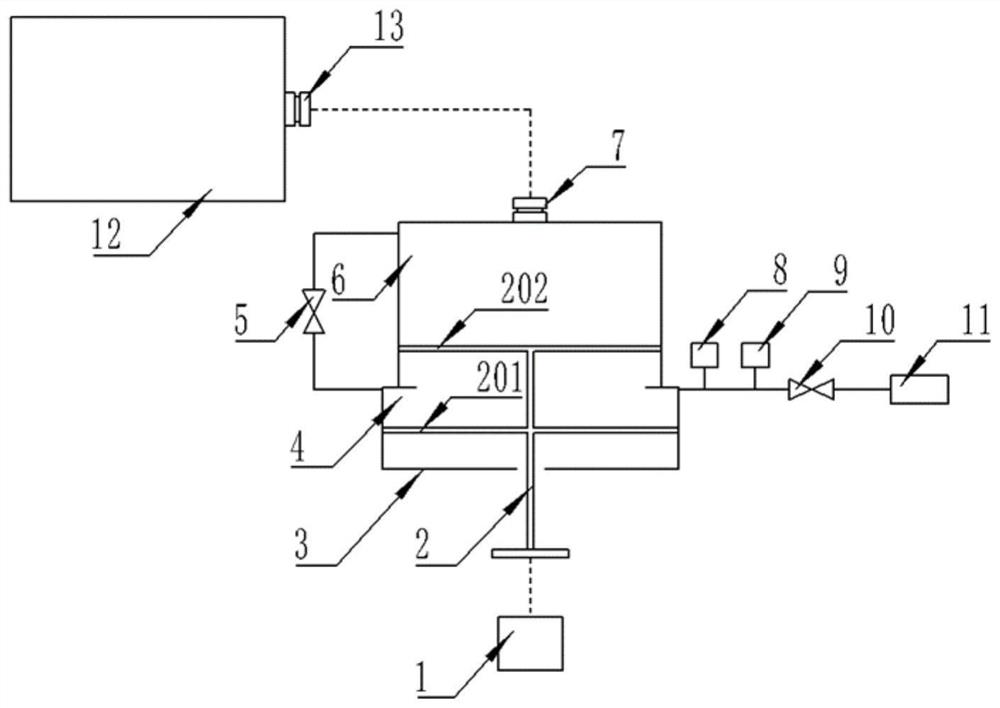
[0068] Such as figure 1 As shown, an on-site density relay calibration device includes a driving mechanism 1, a push rod 2, a first cylinder 3, a first closed space 4, a first valve 5, a second closed space 6, a first quick-plug interface 7, A temperature detection mechanism 8, a pressure detection mechanism 9, a second valve 10, an air circuit interface 11, a second cylinder 12, a second quick-plug interface 13, and a control unit.

[0069] For ease of description and understanding, the figure 1 The middle viewing angle is the main viewing angle, and the up, down, left, and right directions are used as a reference. It should be understood that the setting of the directions is only for the convenience of description and understanding, and should not be construed as a limitation of the present invention.

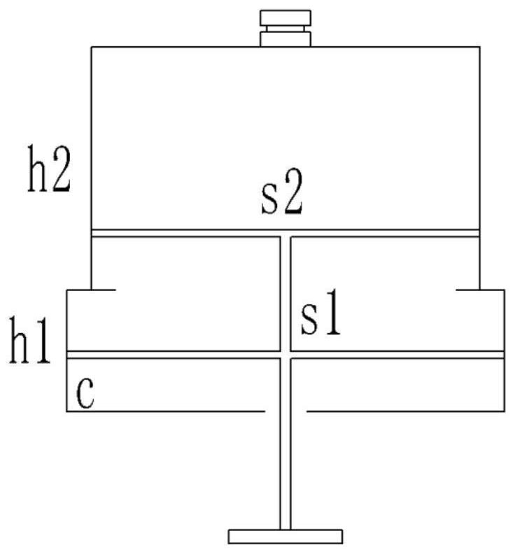
[0070] Such as figure 1 As shown, the first cylinder 3 is provided with a first cavity and a second cavity communicating with each other, and the diameters of the first cav...

Embodiment 2

[0077] The present invention also discloses a verification method using the above-mentioned on-site density relay verification device, which includes the following steps:

[0078] A. Vacuuming:

[0079] Connect the gas circuit interface 11 to the peripheral vacuum equipment, open the first valve 5 and the second valve 10, turn on the vacuum equipment, control the driving mechanism 1 to push the push rod 2, and push the first piston 201 to the first cavity 1. Discharge the remaining gas in the first cylinder 3 from the gas path interface 11 at the variable diameter of the second cavity, and close the first valve 5 and the second valve 10;

[0080] B. Degassing stage:

[0081] Close the valve between the density relay to be calibrated and the air chamber, connect the gas circuit interface 11 to the gas charging port on the side of the density relay to be calibrated, open the first valve 5 and the second valve 10, and connect the side of the density relay to be calibrated The g...


PUM


Abstract

The invention discloses an on-site density relay verification device and a verification method, which include a first cylinder, a first cavity, and a second cavity. A push rod is slidably arranged in the first cylinder, and a drive mechanism is also included; The first piston, the second piston, the space between the first piston and the second piston is the first closed space, the space between the second piston and the inner wall of the first cavity is the second closed space; the first closed space and the second closed space The two closed spaces are communicated through the first pipeline; a second pipeline connected to the first closed space is also included, and a temperature detection mechanism, a pressure detection mechanism, and a second valve are arranged on the second pipeline, and the end of the second pipeline is set The gas path interface also includes a second air cylinder, which is connected to the second closed space. The method includes vacuum pumping, a deflation stage, a pressure boost stage and a pressure drop stage. The invention has the advantages of being able to satisfy both speed and calibration accuracy during actual calibration, and has simple overall structure, convenient operation and low cost.

Description

technical field [0001] The invention relates to the field of density relay calibration, in particular to an on-site density relay calibration device and calibration method. Background technique [0002] SF 6 Switches are high-voltage electrical appliances widely used in power systems, SF 6 The reliable operation of switches has become one of the most concerned issues of power supply and utilization departments. SF 6 The gas density relay is used to monitor the SF in operation 6 SF in switch body 6 An important component of gas density change, its performance directly affects the SF 6 safe operation of the switch. SF running in the field 6 Due to the infrequent action of the gas density relay, after a period of time, the phenomenon of inflexible action and poor contact of the contacts often occurs. In some cases, the temperature compensation performance of the density relay will deteriorate. 6 Density relay malfunctions. Therefore, DL / T596-1996 "Preventive Test Regul...

Claims


Application Information

Patent Timeline
Patent Type & Authority Patents(China)
IPC IPC(8): G01R31/327G01N9/00G01M3/26
CPCG01R31/327G01N9/00G01M3/26
Inventor 王一波吴杨王凤欣谈蓬李秀广马锐方济中韩利潘洁李学锋罗翔宇陈浩宋建华丁五行
Owner ELECTRIC POWER RESEARCH INSTITUTE OF STATE GRID NINGXIA ELECTRIC POWER COMPANY
Why Eureka
Try Eureka