Giant saw disc translation type carrying and stacking equipment
A stacking equipment and translational technology, which is applied in the direction of transportation and packaging, lifting devices, lifting frames, etc., can solve problems such as damage, danger, time-consuming and labor-intensive, and achieve the effect of improving work efficiency
- Summary
- Abstract
- Description
- Claims
- Application Information
AI Technical Summary
Problems solved by technology
Method used
Image
Examples
Embodiment 1
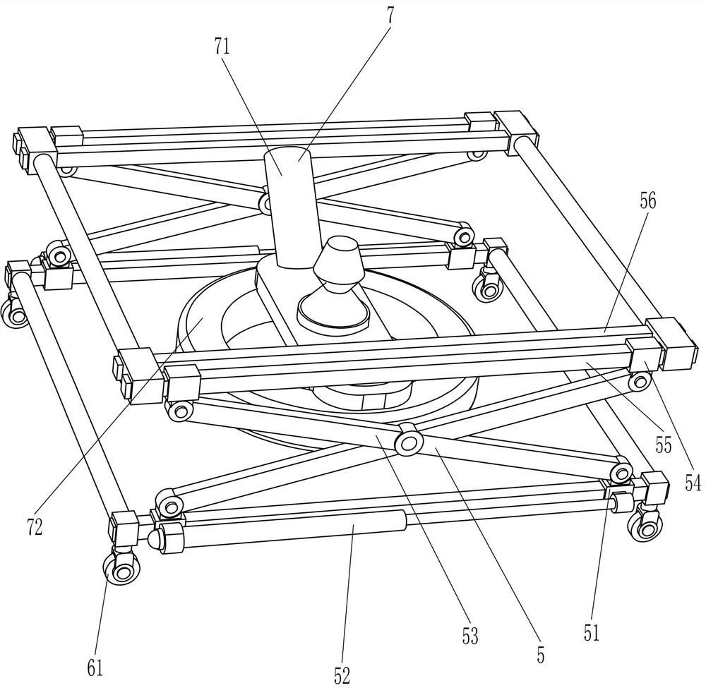
[0042] A giant saw disc translational handling and stacking equipment, such as Figure 1-2 As shown, it includes a round rod 1, a square rod 2, a damping hinge sleeve 3, a push handle 4, a lifting mechanism 5, an auxiliary moving mechanism 6 and a magnetic suction mechanism 7, and a square rod 2 is connected between the front and rear sides of the round rod 1 , the left round rod 1 is connected with a damping hinge sleeve 3 in a rotating manner on both the front and rear sides, a push handle 4 is connected between the top of the damping hinge sleeve 3, a lifting mechanism 5 is connected between the square rod 2, and the round rod 1 is connected with an auxiliary The moving mechanism 6 and the lifting mechanism 5 are connected with a magnetic attraction mechanism 7 .
[0043] When people need to transport the giant saw disc, first hold the push handle 4, push the push handle 4 and the lifting mechanism 5 to move to the position of the giant saw disc, and under the action of the...
Embodiment 2
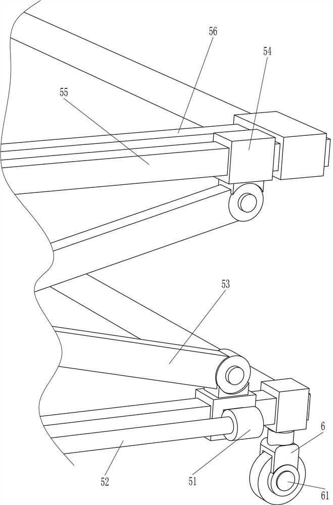
[0045] On the basis of Example 1, as Figure 1-3 As shown, the lifting mechanism 5 includes a square hole sleeve 51, an electric push rod 52, a scissor lift frame 53, a guide sleeve 54, a guide rod 55 and a square frame 56, and the left and right sides of the square rod 2 are slidably connected with square hole sleeves 51. An electric push rod 52 is connected between the sides of the square hole sleeve 51 on the same side, and a scissor lift frame 53 is rotatably connected between the top of the square hole sleeve 51 on the same side. A guide sleeve 54 is connected, and guide rods 55 are slidably connected between the lateral guide sleeves 54 , a square frame 56 is connected between the guide rods 55 , and the inner side of the square frame 56 is connected with the magnetic attraction mechanism 7 .
[0046] When people move the device to the position of the giant saw disc, the magnetic attraction mechanism 7 is activated, so that the magnetic attraction mechanism 7 can attract...
Embodiment 3
[0050] On the basis of Example 2, as figure 2 , 4 As shown in FIG. 5 , the magnetic attraction mechanism 7 includes a fixed plate 71 and an electromagnet 72 , a fixed plate 71 is connected between the front and rear sides of the inner side of the square frame 56 , and an electromagnet 72 is connected to the bottom of the fixed plate 71 .
[0051] When people need to suck the giant saw disc, turn on the electromagnet 72 to fit the giant saw disc and the electromagnet 72. When the giant saw disc is moved to the storage position, turn off the electromagnet 72, and the giant saw can be turned off. The disc is separated from the electromagnet 72 .
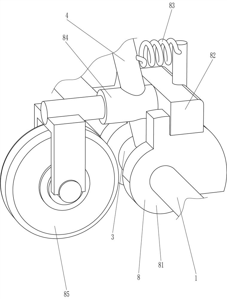
[0052] It also includes a deceleration mechanism 8. The deceleration mechanism 8 includes a fixed block 81, a limit plate 82, a spring 83, a connecting rod 84 and a friction wheel 85. The left round rod 1 is evenly connected to the front and rear sides with a fixed block 81. The fixed block The number of 81 is four, the fixed blocks ...
PUM
 Abstract
Description
Claims
Application Information
 - R&D
- Intellectual Property
- Life Sciences
- Materials
- Tech Scout
- Unparalleled Data Quality
- Higher Quality Content
- 60% Fewer Hallucinations
Browse by: Latest US Patents, China's latest patents, Technical Efficacy Thesaurus, Application Domain, Technology Topic, Popular Technical Reports.
© 2025 PatSnap. All rights reserved.Legal|Privacy policy|Modern Slavery Act Transparency Statement|Sitemap|About US| Contact US: help@patsnap.com


