

Intelligent lock
A technology of smart locks and lock cylinders, applied in building locks, locks operated by mechanical transmission, buildings, etc., can solve problems such as personal injury, delaying the best time for rescue, and increasing the time for unlocking, so as to solve the problem of people trapped. Effect
- Summary
- Abstract
- Description
- Claims
- Application Information
AI Technical Summary
Problems solved by technology
Method used
Image

Examples
Embodiment 1
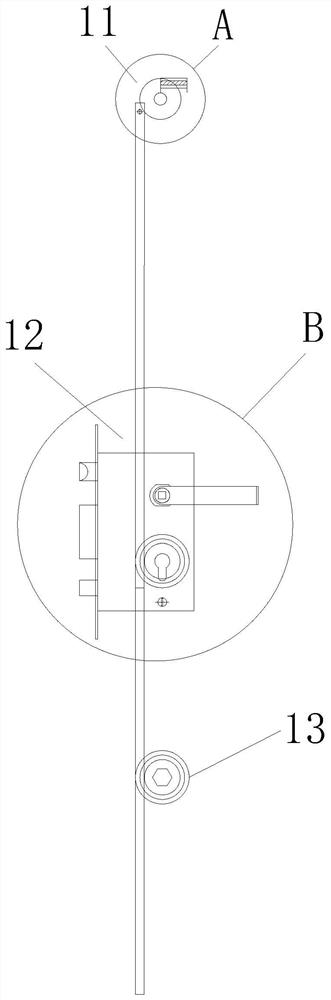
[0035] refer to Figure 1 to Figure 4 As shown, Embodiment 1 of the present invention provides an intelligent lock, which includes a sensing module 11 and an execution module 12. The sensing module 11 is used to monitor whether a fire alarm occurs in real time; The modules 11 are connected, and when a fire alarm is determined in response, the automatic lock 121 is automatically opened without human control, which solves the problem of people being trapped on the one hand, and saves the time for firefighters to break the door on the other hand, which can win more for the rescue work. much time.
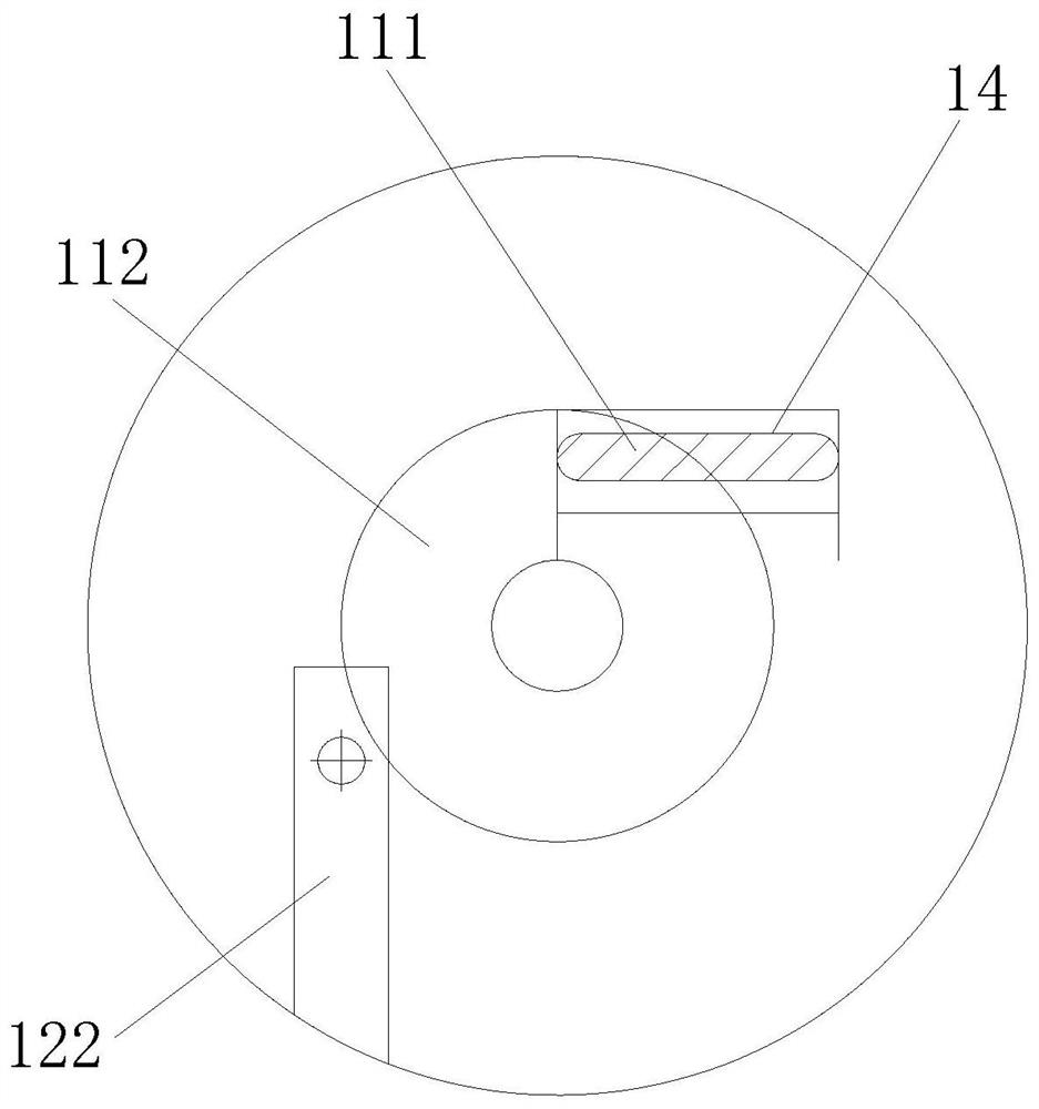
[0036] On the one hand, the induction module 11 includes a temperature sensing element 111 and a release device 112, wherein the temperature sensing element 111 is arranged on the upper part of the door for real-time monitoring of temperature, and when the temperature reaches the limit temperature of the temperature sensing element 111, the temperature sensing element 111 is released. ...
Embodiment 2
[0043] Considering the cost of the transmission device, Embodiment 2 of the present invention provides another smart lock, which includes the various components in Embodiment 1 above, and the same components use the same reference numerals, and this embodiment is not repeated here. repeat. However, the difference is that referring to Figure 5 As shown, the execution module 12 in this embodiment includes a transmission device (the transmission device in Embodiment 2 is different from the transmission device in Embodiment 1), the transmission device includes a transmission part 31 and a connecting part 32, and the transmission part 31 is connected to The connecting parts 32 are connected, the connecting part 32 is connected with the release device 112, and the transmission part 31 is connected with the automatic lock 121. Preferably, the connecting part 32 is a rope, and the transmission part 31 is a rack. The material cost of the device is greatly reduced and is more economic...
Embodiment 3
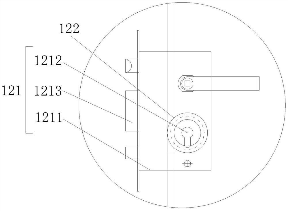
[0046] Embodiment 3 of the present invention provides another smart lock, which includes various components in Embodiment 1 above, and the same components use the same reference numerals, and this embodiment will not be repeated here. However, the difference is that referring to Image 6 As shown, the transmission device in this embodiment includes a torsion spring 41 and a fixed rod 42, and the release device 112 is a spring, wherein the torsion spring 41 is arranged on the lock core part 1212, and the torsion spring 41 undergoes elastic deformation and stores elastic potential energy, so that the lock The core 1212 has a tendency to rotate, but the torsion spring 41 is fixed by the fixed rod 42 and cannot rotate. The other end of the fixed rod 42 is connected to the spring, so that when a fire occurs, the indoor temperature rises. When the temperature reaches the limit temperature, the temperature-sensitive glass ball explodes. At this time, the elastic potential energy of t...
PUM
 Abstract
Description
Claims
Application Information