Layered oil production device with double electric submersible pumps sharing power line

A technology of layered oil production and electric submersible pump, which is applied in the direction of production fluid, earthwork drilling and production, wellbore/well components, etc. It can solve the problem that the size of the cable packer cannot be enlarged, and multiple power cables can not be crossed side by side. Problems such as high cable cost, to achieve the effect of easy installation of power cables, simple commissioning and production, and good production increase effect

Inactive Publication Date: 2021-01-22
陈海荣
View PDF0 Cites 1 Cited by
  • Summary
  • Abstract
  • Description
  • Claims
  • Application Information

AI Technical Summary

Problems solved by technology

[0002] In oil extraction, electric submersible pumps are widely used because of their high efficiency, stability, energy saving and reliability, but in layered oil production, because it is difficult to realize the use of multiple electric submersible pumps, their application This limitation is mainly manifested in the following: (1) Limitation of the cable-passing packer: most of the cable-passing packers currently use the cable-passing packer produced by the American Shell Company. This tool adopts an eccentric structure (including the The oil channel, cable channel, air outlet channel and control line channel generally require a larger oil channel, which causes the entire device to form an eccentric structure, and the space on one side of the cable channel, air outlet channel and control line channel is limited. Adding multiple cable passages will limit the space of downhole pipelines, and the size of the cable packer cannot be enlarged. Therefore, it is impossible to realize the parallel crossing of multiple power cables; (2) The cost of power cables is relatively high: because the power cables are all Specially made, high cost and other factors, in view of the above situation, the invention and implementation of multiple electric submersible pumps share a power line to pass through the cable packer, which can solve the above problems well

Method used


Image

  • Layered oil production device with double electric submersible pumps sharing power line
  • Layered oil production device with double electric submersible pumps sharing power line
  • Layered oil production device with double electric submersible pumps sharing power line

Examples


Embodiment 1

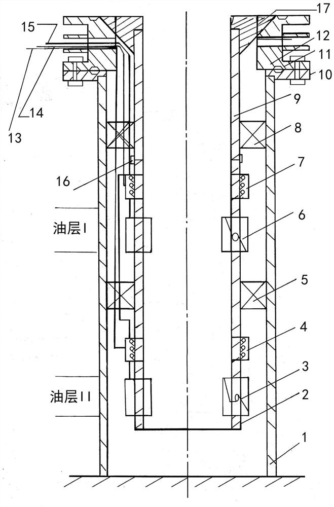
[0036] Embodiment 1, with reference to figure 1 , a layered oil recovery device with dual electric submersible pumps sharing a power line mentioned in the present invention, including a casing 1, a liner 2, a production string 9, a wellhead flange 10, a large cross 12, a hanger 17, a large The spool 12 is installed above the wellhead flange 10, and the production string 9, the electric submersible pump and the liner 2 are lowered into the casing 1 through the hanger 17. It is characterized in that: the electric submersible pump adopts the lower electric submersible pump The submersible pump 6 also includes a lower start switch 4, a lower pass cable packer 5, an upper start switch 7, an upper pass cable packer 8, a lower start switch control line 13, an upper start switch control line 14, and a three-phase power line 15 and phase compensator 16 are connected to the lower ESP 3, the lower start switch 4, the lower pass cable packer 5, the upper ESP 6, the upper start switch 7, t...

Embodiment 2

[0062] Embodiment 2, a layered oil recovery device with dual electric submersible pumps sharing power lines mentioned in the present invention, including casing 1, liner 2, production string 9, wellhead flange 10, large cross 12, hanger 17. The large cross 12 is installed above the wellhead flange 10, and the production string 9, the electric submersible pump and the liner 2 are lowered into the casing 1 through the hanger 17, and the feature is that the electric submersible pump adopts the lower electric submersible pump 3 and the upper electric submersible pump 6, and also includes a lower start switch 4, a lower pass cable packer 5, an upper start switch 7, an upper pass cable packer 8, a lower start switch control line 13, an upper start switch control line 14, three The phase power line 15 and the phase compensator 16 are connected to the lower electric submersible pump 3, the lower start switch 4, the lower pass cable packer 5, the upper electric submersible pump 6, the u...


PUM


Abstract

The invention relates to a layered oil production device with double electric submersible pumps sharing a power line. According to the technical scheme, a lower-layer starting switch and a lower-layerelectric submersible pump are arranged below a lower-layer cable passing packer, and an upper-layer electric submersible pump, an upper-layer starting switch and a phase compensator are arranged between the lower-layer cable passing packer and an upper-layer cable passing packer; and a second power cable of the lower-layer electric submersible pump is upwards connected to a first power cable of the upper-layer electric submersible pump in parallel along the lower-layer cable passing packer, and a lower-layer starting switch control line of the lower-layer electric submersible pump moves alongthe lower-layer cable passing packer, the upper-layer cable passing packer, and penetrates through a threading hole of a large four-way joint of a wellhead with an upper-layer starting switch controlline. The layered oil production device with the double electric submersible pumps sharing the power line has the advantages that the structure of an underground power cable is simplified, the problem that a cable passing packer with an eccentric structure cannot penetrate into two sets of power cables is solved, the purpose that the two electric submersible pumps are used for underground layeredoil production is achieved, oil production layers are clearer, production allocation is achieved through electric control, and efficient oil production is achieved.

Description

technical field [0001] The invention relates to an electric submersible pump oil production device and method, in particular to a layered oil production device with two electric submersible pumps sharing a power line. Background technique [0002] In oil extraction, electric submersible pumps are widely used because of their high efficiency, stability, energy saving and reliability, but in layered oil production, because it is difficult to realize the use of multiple electric submersible pumps, their application This limitation is mainly manifested in the following: (1) Limitation of the cable-passing packer: most of the cable-passing packers currently use the cable-passing packer produced by the American Shell Company. This tool adopts an eccentric structure (including the The oil channel, cable channel, air outlet channel and control line channel generally require a larger oil channel, which causes the entire device to form an eccentric structure, and the space on one side...

Claims


Application Information

Patent Timeline
Patent Type & Authority Applications(China)
IPC IPC(8): E21B43/14E21B43/00
CPCE21B43/128E21B43/14
Inventor 陈海荣宋媛媛
Owner 陈海荣
Why Eureka
Try Eureka