
Automatic inflow water control device and water control method thereof

A technology of water control device and inflow control, which is applied in wellbore/well valve device, production fluid, earth-moving drilling, etc. The effect of liquid production

Pending Publication Date: 2021-12-07
STARSE ENERGY & TECH GROUP
View PDF0 Cites 0 Cited by
  • Summary
  • Abstract
  • Description
  • Claims
  • Application Information

AI Technical Summary

Problems solved by technology

However, some technologies must obtain oil well data in advance to design and carry out on-site adjustments. Due to structural limitations, it is difficult for these water control technologies to achieve water control throughout the cycle
[0004] In some oil and gas fields, high-efficiency water control is required in the early stage, high-yield liquid extraction and water control can be carried out in the later stage, and acid injection can also be used to increase production in the later stage. At present, the existing automatic inflow water control screens cannot achieve the goal of comprehensive production increase. In the later stage, operations such as acid injection to increase production or water injection cannot be effectively performed, so the production efficiency cannot be maximized

Method used


Image

  • Automatic inflow water control device and water control method thereof
  • Automatic inflow water control device and water control method thereof
  • Automatic inflow water control device and water control method thereof

Examples


Embodiment Construction

[0057] Below in conjunction with accompanying drawing, structure principle and working principle of the present invention are described in detail:

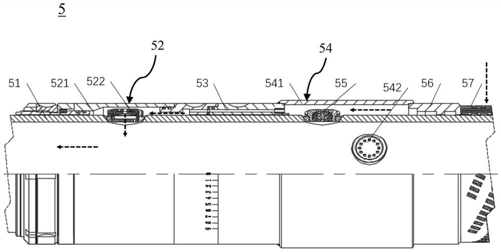
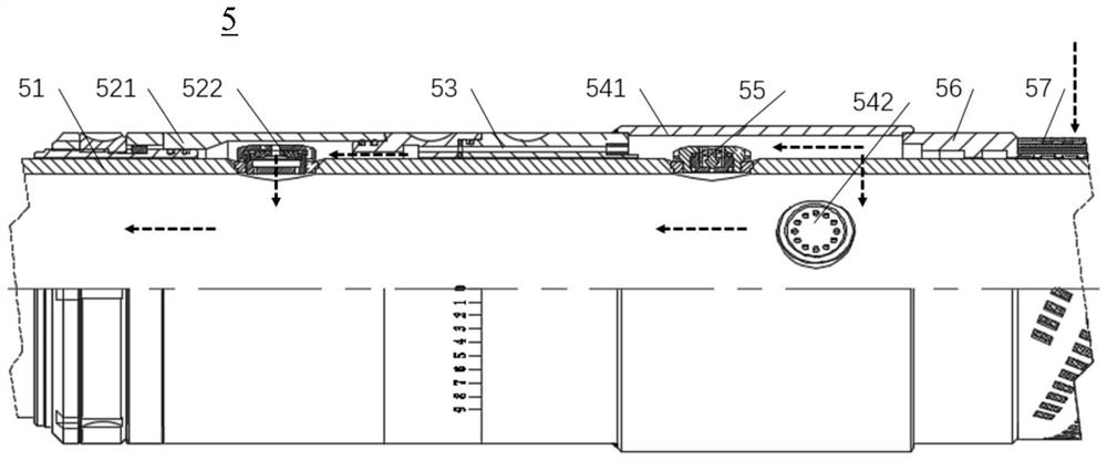
[0058] see figure 1 and figure 2 , figure 1 It is a schematic diagram of the arrangement of the downhole pipe string according to an embodiment of the present invention, figure 2It is a schematic structural diagram of the automatic inflow water control device 5 according to an embodiment of the present invention (conventional current-limiting state). The automatic inflow water control device 5 of the present invention can increase production and can inject liquid, and it is a plurality of connected together, combined into the well, the whole pipe string is communicated with the ground 1 through the oil pipe 2, the top packer 3 and the middle packer 6 (such as an open hole packer or a continuous packer) according to the well condition, the wellbore 4 is divided into multiple sections, and the guide shoe 7 guides the pipe strin...


PUM


Abstract

The invention discloses an automatic inflow water control device and a water control method thereof. The automatic inflow water control device comprises a base pipe, a self-adaptive internal flow control mechanism, an inflow control mechanism, a yield increasing inflow control mechanism and a fluid injection one-way flowing device; the self-adaptive internal flow control mechanism is installed on the base pipe and comprises a self-adaptive internal flow controller and a self-adaptive outer sleeve, the self-adaptive internal flow controller is provided with a channel used for communicating the inside and the outside of the base pipe, and the opening degree of the channel is adjusted to automatically limit the flow according to different viscosities of fluid flowing through the self-adaptive internal flow controller; the inflow control mechanism is arranged on the base pipe in a sleeve manner and is connected to the self-adaptive outer sleeve; the yield increasing inflow control mechanism is installed on the base pipe and comprises a yield increasing sleeve and a yield increasing inflow controller, the yield increasing inflow controller is provided with a yield increasing channel used for communicating the interior and the exterior of the base pipe, and the yield increasing channel is controlled to be opened or closed according to the production pressure difference or the set designated opening pressure difference; and the fluid injection one-way flowing device is used for ensuring that the liquid injected from a wellhead can only flow into a stratum from the base pipe in a single direction. The invention further provides a water control method of the water control device.

Description

technical field [0001] The invention relates to a water control technology for horizontal wells, in particular to an automatic inflow water control device capable of increasing production and injecting liquid and a water control method thereof. Background technique [0002] In the current oil and natural gas extraction process, horizontal wells have been widely developed and applied due to their advantages of high liquid production, small production pressure difference, and small flow resistance. Horizontal wells are characterized by an unbalanced flow profile. With the extension of production time, this unbalanced flow profile will lead to premature water breakthrough, reduce well life, and affect well productivity. [0003] The existing horizontal well water control technology adopts two methods: one is the passive water control method of first finding water and then controlling the water. This method is carried out in the production state, the construction process is comp...

Claims


Application Information

Patent Timeline
Patent Type & Authority Applications(China)
IPC IPC(8): E21B34/08E21B43/08E21B43/22
CPCE21B34/08E21B43/086E21B43/16
Inventor 易齐尊刘孝强谭章龙唐少鹏陈善饮李伯仁林德纯陈光利朱长林刘妙仁
Owner STARSE ENERGY & TECH GROUP
Learn More