Novel laser projection illuminating system

A technology of laser projection and lighting system

Inactive Publication Date: 2017-08-15
成都九天光学技术有限公司
View PDF6 Cites 6 Cited by
  • Summary
  • Abstract
  • Description
  • Claims
  • Application Information

AI Technical Summary

Problems solved by technology

In the process of coupling the laser to the optical fiber, a complex optical fiber coupling optical system is required. At the same time, the laser energy loss is also very large during the coupling process. At the same time, a complex laser speckle system needs to be added to the optical path. The optical path and structure of the entire system They are very complicated, require very high assembly precision, and are expensive, so they cannot be used in civilian laser display products.

Method used


Image

  • Novel laser projection illuminating system
  • Novel laser projection illuminating system
  • Novel laser projection illuminating system

Examples


Embodiment Construction

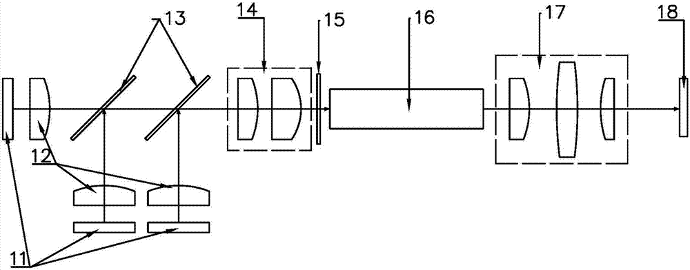
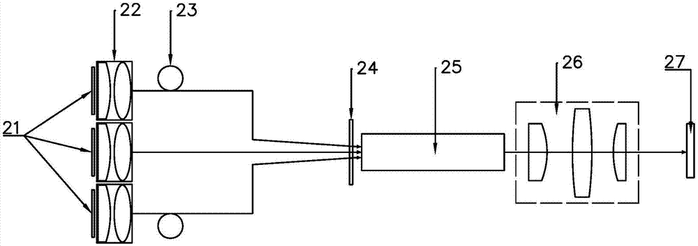
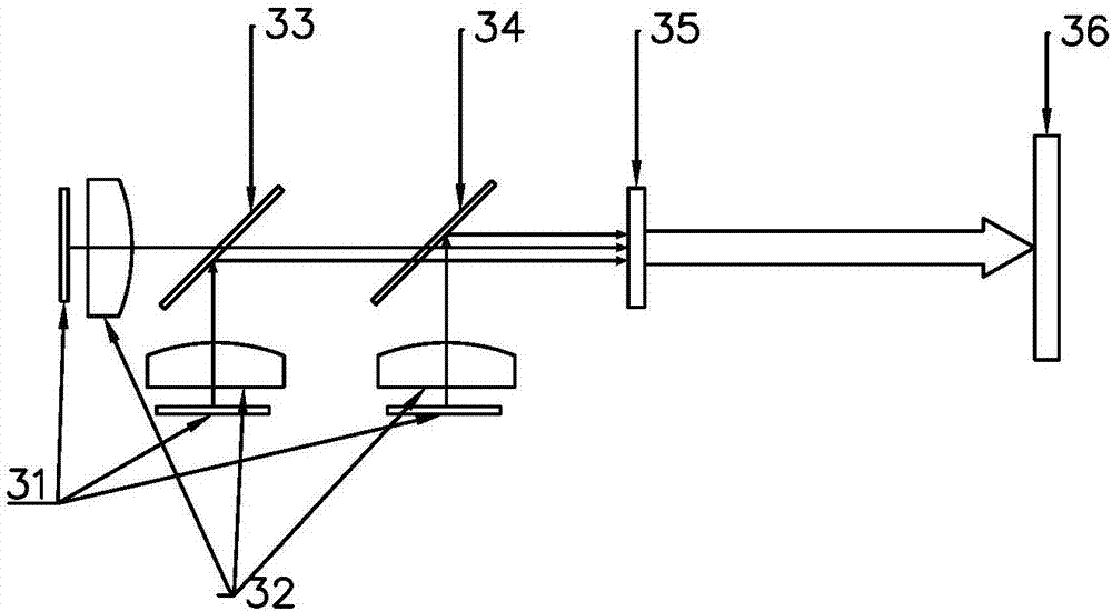
[0023] Below in conjunction with accompanying drawing and specific embodiment, the present invention will be further described, and for the convenience of description and corresponding comparison, in the prior art illustration ( figure 1 , figure 2 ) and diagrams showing specific embodiments of the invention ( image 3 , Figure 4 ), different numbers are used for parts with the same function, but the same technical name is still used.

[0024] Such as image 3 As shown, the novel laser projection lighting system of the present invention is composed of a laser light source 31 , a collimation compression system 32 , dichroic mirrors 33 and 34 , a binary optical element 35 , and a DMD chip 36 . A laser light source 31 , a collimating compression system 32 , dichroic mirrors 33 , 34 , a binary optical element 35 and a DMD chip 36 are arranged in sequence from left to right. Here, left and right refer to the propagation direction of the light emitted by the laser light source...


PUM


Abstract

The invention discloses a novel laser projection illuminating system, which comprises a laser light source, a collimation and compression system, a dichroic mirror, a binary optical element and a DMD chip, wherein the laser light source emits laser to be compressed by means of the collimation and compression system, the laser maintains parallel light emission and illuminates onto the dichroic mirror for beam splitting, and the laser is incident onto the binary optical element and reaches the DMD chip through the binary optical element; and the binary optical element is used for shaping the incident laser according to a proportion of an adopted display chip, and/or performing speckle-elimination processing on the incident laser. The novel laser projection illuminating system is simple and compact in structure, increases the optical efficiency by more than one time when compared with an illuminating system used at present, is simple in assembly and production, effectively improves the installation reliability and the production efficiency, is high in utilization rate, is suitable for scale production, and is worth popularizing in the industry.

Description

technical field [0001] The invention belongs to the technical field of laser projection, and in particular relates to a novel laser projection lighting system. Background technique [0002] As the fourth generation of TV, laser TV is a current research hotspot. In the existing lighting system, the light source adopts the following implementation scheme: [0003] (1) Laser and fluorescent mixed light source; [0004] (2) Laser + LED hybrid light source; [0005] (3) Laser + fluorescent + LED mixed light source; [0006] (4) Red, green, blue three-color pure laser light source; [0007] Among them, due to the advantages of laser monochromaticity, high color purity, high brightness, and small numerical aperture, it can be used in large-screen laser TVs, so the (4) solution becomes the future development direction of the laser projection field, but this solution Among them, the biggest challenge comes from the fact that the laser speckle is not easy to eliminate, especially...

Claims


Application Information

Patent Timeline
Patent Type & Authority Applications(China)
IPC IPC(8): G03B21/20
CPCG03B21/2033G03B21/208
Inventor 吴新民
Owner 成都九天光学技术有限公司
Why Eureka
Try Eureka