


Quick Research
Generate reliable direction feasibility study reports for your R&D in just a few steps.

Technical Q&A
Discover and master advanced knowledge NOW. Basics, ideas, possibilities, all at once.

Find Solutions
As an expert in R&D theories, this can generate solutions to your technical problems instantly.

Evaluate Feasibility
Analyze your overall solution with one click, know your potential R&D risks in advance.

Monitor Landscape
Get weekly tech updates, stay abreast of the latest tech innovations and key insights.
U-shaped inward-folding rotating mechanism straight sliding groove bending
A rotating mechanism and straight-slip technology, applied in pivot connections, instruments, identification devices, etc., can solve the problems of inconvenient industrial manufacturing and large number of spare parts, and achieve the effect of simple and effective structural design and easy industrial implementation.
- Summary
- Abstract
- Description
- Claims
- Application Information
AI Technical Summary
Problems solved by technology
Method used
Image

Examples
Embodiment 1
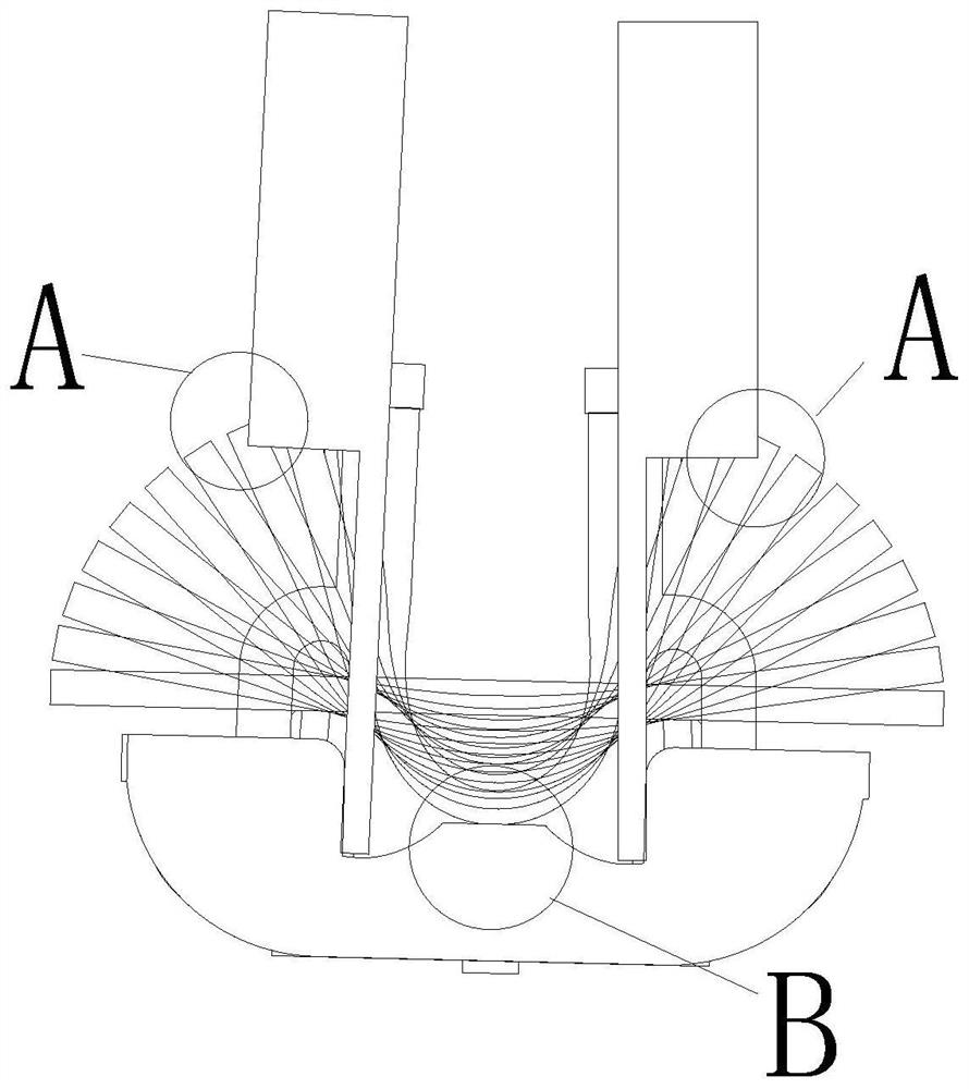
[0038] In this example, if figure 2 As shown, A is the stroke change of the flexible screen during the bending process, and B is the relationship between the angle change of the mechanism rotation process and the position change of the screen, that is, the sliding constant length refers to the flexible screen during the whole bending process. The relative position of the rotating shaft 11 does not change, and the position adjustment during the bending process is satisfied through the change of the mechanism, so that the constant length during the bending process of the flexible screen does not change.
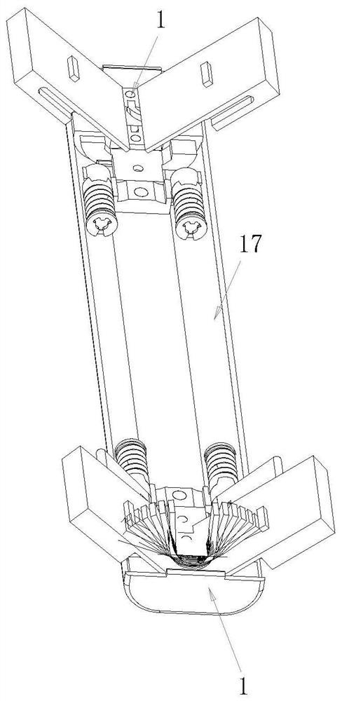
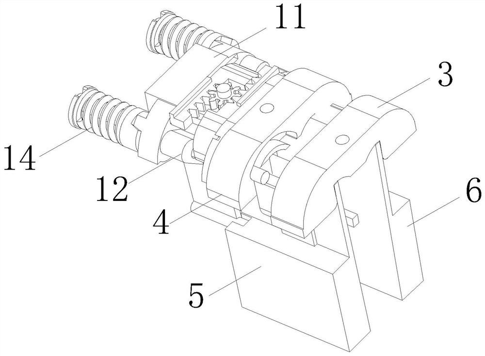
[0039] Such as Figure 1-19 As shown, the U-shaped inward turning mechanism disclosed in this embodiment includes a structural main body, and the structural main body includes two sets of rotating shafts 1, and the rotating shaft 1 includes a rotating mechanism 2, and the rotating mechanism 2 includes a longitudinal The first fixed frame 3 and the second fixed frame 4 that ar...
PUM
 Abstract
Description
Claims
Application Information
 - R&D Engineer
- R&D Manager
- IP Professional
- Industry Leading Data Capabilities
- Powerful AI technology
- Patent DNA Extraction
Browse by: Latest US Patents, China's latest patents, Technical Efficacy Thesaurus, Application Domain, Technology Topic, Popular Technical Reports.
© 2024 PatSnap. All rights reserved.Legal|Privacy policy|Modern Slavery Act Transparency Statement|Sitemap|About US| Contact US: help@patsnap.com