Self-operated piston valve

A piston valve, self-operated technology, applied in the field of self-operated piston valve, can solve the problems of operation and maintenance limitations and troubles in application conditions, and achieve the effect of convenient follow-up maintenance, simplified and lightweight structure

Pending Publication Date: 2021-01-22
湖南泵阀制造有限公司
View PDF2 Cites 0 Cited by
  • Summary
  • Abstract
  • Description
  • Claims
  • Application Information

AI Technical Summary

Problems solved by technology

However, the current piston valves are all driven by external forces, such as Chinese patents 201610256810.2 and 201420239851.7, the opening and closing parts are driven by the crank connecting rod mechanism, and the valve is opened and closed by moving forward an

Method used


Image

  • Self-operated piston valve
  • Self-operated piston valve
  • Self-operated piston valve

Examples


Example Embodiment

[0029]The embodiments of the present invention are described in detail below. Examples of the embodiments are shown in the accompanying drawings, wherein the same or similar reference numerals represent the same or similar elements or elements with the same or similar functions. The embodiments described below with reference to the drawings are exemplary, and are only used to explain the present invention, but should not be understood as limiting the present invention.

[0030]In the description of the present invention, it should be understood that the terms "center", "longitudinal", "transverse", "length", "width", "thickness", "upper", "lower", "front", " "Back", "Left", "Right", "Vertical", "Horizontal", "Top", "Bottom", "Inner", "Outer", "Axial", "Radial", "Circumferential" The orientation or positional relationship of other indications is based on the orientation or positional relationship shown in the drawings, which is only used to facilitate the description of the present inve...


PUM


Abstract

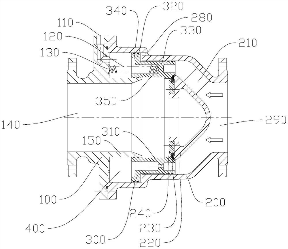
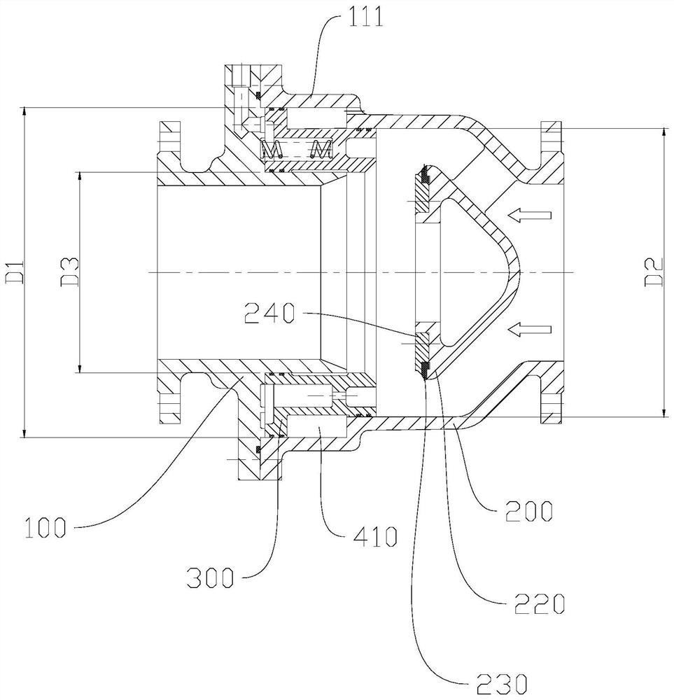
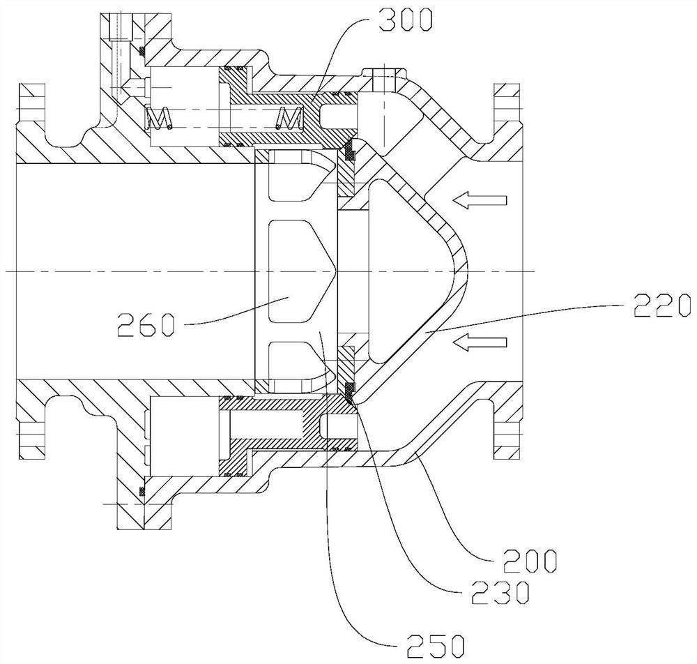
The invention discloses a self-operated piston valve. The self-operated piston valve comprises a valve body and a piston body, the valve body is provided with an inlet end and an outlet end, a flow deflector is arranged at the inlet end, the piston body is arranged in the valve body, an end surface, close to the inlet end, of the piston body is used for cooperating with the flow deflector to closethe valve, a spring is arranged between an end surface of the outlet end of the piston body and the valve body, the spring is used for pushing the piston body to move towards the flow deflector, endsurfaces, close to the outlet end, of the valve body and the piston body form a pressure cavity, the pressure cavity communicates with the inlet end through a communication hole formed in the piston body, and the valve body is provided with an external connection hole extending to the pressure cavity. According to the self-operated piston valve, the medium pressure in the valve body serves as a driving force, the pressure in the pressure cavity is controlled through the external connection hole and the communication hole which communicate with the pressure cavity, the piston body is driven toaxially move in the valve body, and opening and closing of the valve are achieved. The structure is simple and light, the maintenance is simple, and the configuration mode of the external connection hole can be flexibly selected.

Description

technical field [0001] The invention relates to a hydraulic control valve, in particular to a self-operated piston valve. Background technique [0002] At present, the hydraulic control valve uses the pressure of the pipeline medium as the power to realize the opening and closing and adjustment of the valve. There are two types of diaphragm type and piston type. The differential principle realizes the opening, closing or adjusting state of the disc. Its main valve body is Y-shaped, T-shaped and other cut-off forms. The valve structure is complicated and the volume is large, which is not conducive to miniaturization and convenient application. Due to the twists and turns of its flow path, the adjustment performance is poor, especially not suitable for high pressure differential conditions. [0003] At the same time, the currently widely used piston valve (also known as flow regulating and pressure regulating valve) has good flow and pressure regulating performance due to it...

Claims


Application Information

Patent Timeline
IPC IPC(8): F16K1/00F16K1/32F16K1/38F16K31/363
CPCF16K1/00F16K1/32F16K1/38F16K31/363
Inventor 朱铁强邱荣水黄海嵩
Owner 湖南泵阀制造有限公司
Why Eureka
Try Eureka