
Test piece mechanism of high-pressure compressor

A compressor and test piece technology, applied in jet engine testing, gas turbine engine testing, etc., can solve the problem that the test results of components cannot fully reflect the working environment

Active Publication Date: 2021-01-22
AECC SHANGHAI COMML AIRCRAFT ENGINE MFG CO LTD +1
View PDF7 Cites 1 Cited by
  • Summary
  • Abstract
  • Description
  • Claims
  • Application Information

AI Technical Summary

Problems solved by technology

[0012] The technical problem to be solved by the present invention is to overcome the defect that there is a certain difference between the high-pressure compressor component test and the complete machine test in the prior art, and the obtained component test results cannot fully reflect the working environment under the complete machine state, and provide a high-pressure compressor machine test piece mechanism

Method used


Image

  • Test piece mechanism of high-pressure compressor
  • Test piece mechanism of high-pressure compressor
  • Test piece mechanism of high-pressure compressor

Examples


Embodiment Construction

[0047] In order to make the above objects, features and advantages of the present invention more comprehensible, specific implementations of the present invention will be described in detail below in conjunction with the accompanying drawings.

[0048] Embodiments of the present invention will now be described in detail with reference to the accompanying drawings. Reference will now be made in detail to the preferred embodiments of the invention, examples of which are illustrated in the accompanying drawings. Wherever possible, the same numbers will be used throughout the drawings to refer to the same or like parts.

[0049] In addition, although the terms used in the present invention are selected from well-known and commonly used terms, some terms mentioned in the description of the present invention may be selected by the applicant according to his or her judgment, and the detailed meanings thereof are set forth herein described in the relevant section of the description. ...


PUM


Abstract

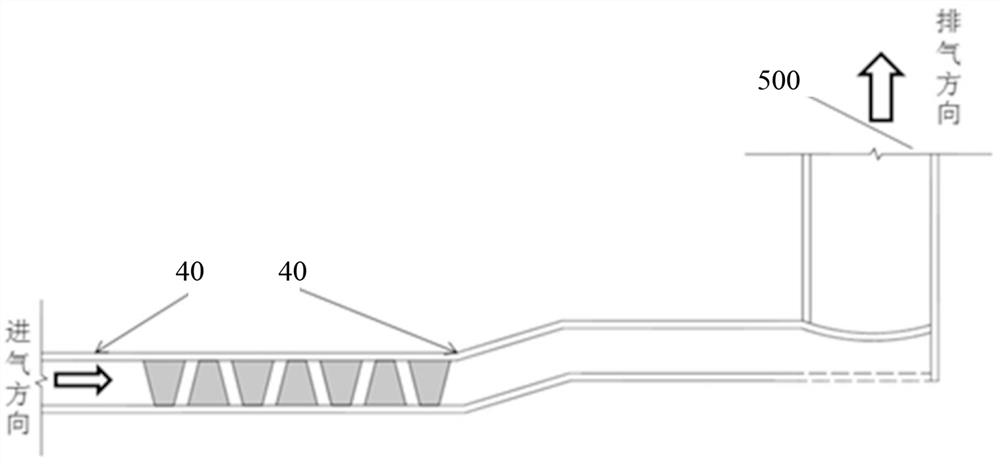
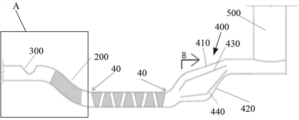
The invention provides a test piece mechanism of a high-pressure compressor. The mechanism is used for simulating the working environment of a whole turbofan engine and comprises a high-pressure compressor body, an inlet support plate and a transition section flow channel are arranged at the inlet of the high-pressure compressor body, a distortion device is arranged at the upstream of the inlet support plate and the transition section flow channel, and the distortion device is positioned in an outer flow channel of the inlet support plate and the transition section flow channel. The inventionprovides a high-pressure compressor test structure form capable of accurately simulating a complete machine environment. The high-pressure compressor test structure form comprises an inlet distortiondevice form, a high-pressure compressor body and an outlet simulation combustion chamber form. Meanwhile, a set of high-pressure compressor inlet distortion device structure scheme is provided, an inlet pressure profile can be generated, and the profile is consistent with the inlet pressure profile of the high-pressure compressor in the whole machine environment.

Description

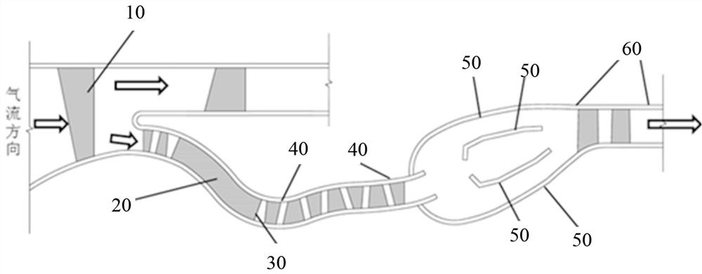
technical field [0001] The invention relates to the field of a turbofan engine high-pressure compressor test piece, in particular to a high-pressure compressor test piece mechanism. Background technique [0002] figure 1 It is a schematic diagram of the overall structure of a typical turbofan engine in the prior art. [0003] Such as figure 1 As shown, in the prior art, a typical civil turbofan aeroengine is usually a double-duct configuration. During the whole machine test, after the air flows into the engine from the air inlet of the aircraft, it first enters the engine body through the fan 10, and then flows through the splitter ring and is divided into two parts, one part is discharged from the engine through the outer culvert, and the other part flows into the high pressure through the channel 20 of the transition section of the support plate. compressor. Wherein, the outlet position 30 of the support plate belongs to the interface of the high and low pressure air m...

Claims


Application Information

Patent Timeline
IPC IPC(8): G01M15/14
CPCG01M15/14
Inventor 翟志龙曹传军尹泽勇李继保姜逸轩李游
Owner AECC SHANGHAI COMML AIRCRAFT ENGINE MFG CO LTD
Learn More