[0050]In order to make the objectives, technical solutions, and advantages of the embodiments of the present invention clearer, the technical solutions in the embodiments of the present invention are described clearly and completely below. Obviously, the described examples are part of the embodiments of the present invention, not all of them. example. Based on the embodiments of the present invention, all other embodiments obtained by those of ordinary skill in the art without creative work shall fall within the protection scope of the present invention.
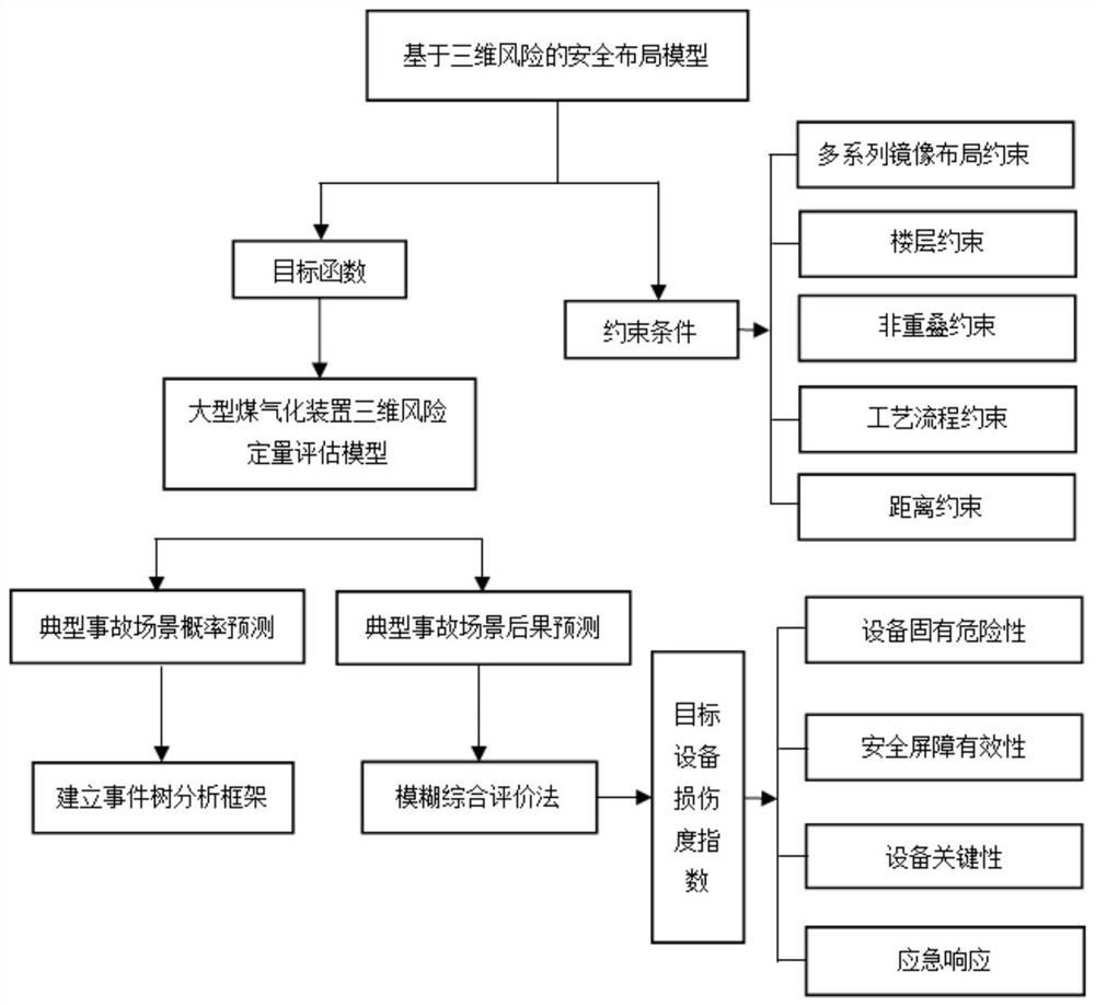
[0051]Such asfigure 1 As shown, a method for the safe layout of a large-scale coal gasification unit is to establish a three-dimensional risk assessment model to minimize the three-dimensional risk value as the objective function. According to actual engineering requirements, multiple series of layout constraints and process flows are further added to the optimization model. Constraints make the obtained equipment layout more in line with engineering requirements. In the quantitative risk assessment, the fuzzy comprehensive evaluation method is used to quantitatively calculate the influencing factors of the target equipment damage level in different accident scenarios. This model can realize the superimposition calculation of the risk value in the multi-accident scenario and use the GAMS software to obtain the optimum Solution, the detailed method steps are as follows:
[0052]1. Establish a three-dimensional risk assessment model for large-scale coal gasification plants
[0053]According to the QRA method, it can be known that the three-dimensional risk to the risk receptor caused by the occurrence of different accident types at a certain point in space by the hazard source can be expressed by the following formula:
[0054]
[0055]In the formula, i represents the dangerous source equipment, j represents the affected target equipment, piIndicates the failure probability of different accident types in the hazard, pij Indicates the probability of domino failure of the target device, EDIjIndicates the damage index of the target equipment, h represents the accident type, and n is the number of equipment in the evaluation area.
[0056]2. Establish the objective function of the multi-series mirror image layout of the large-scale coal gasification plant
[0057]In order to obtain the safe layout of chemical equipment in space, the objective function is expressed as the minimization of the three-dimensional risk value of the initial equipment, and the safety goal is represented by the sum of the three-dimensional risks of the hazard source equipment at a specific location to the target equipment. The objective function is as follows:
[0058]
[0059]In the formula, i represents the dangerous source equipment, j represents the affected target equipment, piIndicates the failure probability of different accident types in the hazard, pij Indicates the probability of domino failure of the target device, EDIjIndicates the damage index of the target equipment, h represents the accident type, and n is the number of equipment in the evaluation area.
[0060]Make the following assumptions based on the actual situation:
[0061](1) The number and dimensions of the equipment to be laid out in the area are known, and the appearance of all equipment is approximately cylindrical. The dimensions and parameters of each equipment are shown in Table 1:
[0062]Table 1 Equipment parameters of a coal water slurry gasification process
[0063]
[0064](2) The frame and the system unit are rectangular, the boundary of the system unit has been determined and the length and width are known. The coal gasification process equipment layout plan uses 3 series (A series, B series and C series) as a joint production area. For equipment Layout A series, B series and C series adopt mirror image arrangement, the schematic model of system unit and equipment is as followsfigure 2 As shown; the rectangular area does not actually exist, just for the layout of each device in the system within the area size, and each rectangular area is laid out according to multiple lines of straight lines, divided into several rows and the size of each row is the same, and the size of each unit Determined according to the frame size;
[0065](3) There are 6 main equipments in the process. The gasification furnace, slag lock bucket and washing tower are gasification units, and the high-pressure flash tank, vacuum flash tank and high-pressure flash separation tank are black water units for the convenience of construction. Models, A series, B series and C series share a frame. The gasification unit and the black water unit are separated by a firewall. The height of the gasification furnace, washing tower and vacuum flash tank are all higher than the height of the floor. The frame has 7 floors. , And the height of each floor is not equal, the frame building height is 55.0m;
[0066](4) For the three-dimensional space layout, in order to indicate the location of each device, first establish a coordinate system: the lower left corner of the two-dimensional plane of the layout area is the zero point, the right is the horizontal positive direction (x axis), and the upward is the vertical positive direction (y Axis), which is the positive direction perpendicular to the two-dimensional plane (z axis).
[0067]Specifically, the step 2 specifically includes:
[0068](1) Calculation of the probability of initial accident
[0069]Select the device number in the system unit is G3The scrubber is a hazard source, the accident scene is a vapor cloud explosion (VCE), the scrubber syngas leakage rate is 0.41kg/s, the leakage time is 10min, and the probability of occurrence is assumed to be 1. For simplicity, assume the explosion center, gas cloud center and The center of the scrubber is coincident.
[0070](2) Calculation of failure probability of target equipment
[0071]When the physical effect of the initial accident acts on the target device, the target device will be destroyed with a certain probability, and a domino accident will occur. Because of its simplicity and flexibility, the Probit method is widely used to estimate the probability of equipment upgrades and can be applied to many types of equipment. The Probit method can simultaneously consider the type of equipment (such as normal pressure or pressurized) and the type of upgrade vector received by the equipment (such as thermal radiation or explosive overpressure) to calculate the probability value Y. The probability value calculation formula is shown in Table 2.
[0072]Table 2 Probability value calculation formula
[0073]
[0074]After Y is determined, the upgrade probability can be calculated as:
[0075]
[0076](3) Target Equipment Damage Index (EDIj) Calculation
[0077]Specifically, the step (3) specifically includes:
[0078](31) Four important indicators are selected, U = {u1,u2,u3,u4} = {Equipment inherent hazard, safety barrier effectiveness, equipment criticality, emergency response time};
[0079](32) The evaluation set of damage evaluation is divided into three grades, V={severe, moderate, minor}, the final target equipment degree evaluation result is obtained from the evaluation set V. The criteria for the classification of indicators are shown in Table 3, with different damage degrees See Table 4 for grade division and grade connotation;
[0080]Table 3 Target equipment damage level table
[0081]
[0082]Table 4 Equipment damage degree classification and description
[0083] Damage level Weighted value Standard score Description serious 1.0 (0.7,1.0] The target device is completely damaged and the device is scrapped medium 0.7 (0.3,0.7] The target equipment is partially damaged and needs to be stopped for maintenance slight 0.3 (0,0.3] The target equipment is slightly damaged, and production can be resumed immediately after overhaul
[0084](33) The four first-level index weights obtained using tomographic analysis are: equipment hazard, safety barrier effectiveness, equipment importance, emergency response time (0.626, 0.146, 0.173, 0.055);
[0085](34) Carry out single-factor fuzzy evaluation based on the single index among the above indexes, determine the evaluation fuzzy matrix, and obtain the damage degree index results of each equipment as shown in Table 5:
[0086]Table 5 Damage degree index of each equipment
[0087] Equipment label 1 2 3 4 5 6 ID i
[0088]3. Establish constraints for the multi-series mirroring layout of large-scale coal gasification plants
[0089]Specifically, the step (3) specifically includes:
[0090](31) Multi-series mirroring layout constraints
[0091]
[0092]
[0093]xi≤[lu-Dw-rad(i)]+(e-1)·lu
[0094]xi≥rad(i)+Du+(e-1)·lu
[0095]yi≤(wu-Dw-rad(i))+(e-1)·wu
[0096]yi≥rad(i)+Dw+(e-1)·wu
[0097](32) Floor constraints
[0098]
[0099]
[0100]
[0101]Nij ≥Vik +Vjk-1
[0102]
[0103]Nij ≤1-Vik +Vjk
[0104]
[0105]Nij ≤1+Vik -Vjk
[0106]
[0107](33) Non-overlapping constraints
[0108]
[0109]
[0110]
[0111]
[0112](34) Process flow constraints
[0113]zj-zi+BM(1-UPij )≥(γi+γj)/2
[0114]zi-zj+BM(1-DOij )≥(γi+γj)/2
[0115]xi-xi=BM(1-UPij )
[0116]yi-yi=BM(1-UPij )
[0117](35) Distance constraint
[0118]Use Euclidean distance to calculate the center distance of two devices, the equation is:
[0119]
[0120]The parameter descriptions in the above constraints are shown in Table 6.
[0121]Table 6 Model parameter description
[0122]
[0123]
[0124]4. Use the DICOPT solver in the GAMS software to solve the model, and the minimum three-dimensional risk is 5.12. Table 7 shows the center point coordinates and floor distribution of each device. The safety layout plan is as followsimage 3 As shown, the three-dimensional layout is asFigure 4 Shown.
[0125]Table 7 Safety layout parameters of system units
[0126]
[0127]
[0128]From the calculation results, it can be found that in a limited space, the horizontal arrangement of the system unit is less risky than the vertical arrangement of the three-dimensional. The dangerous source equipment is placed in the corner, and the damage index (ID) of the scrubber is high, that is, the consequences to it are more serious in different accident scenarios. The equipment with high damage index of the target equipment is placed far away from the source of danger to reduce the influence of the domino effect on other system units. The location of the gasifier is also worth noting. The damage index (ID) of the gasifier is the highest. However, due to the strong connection between the gasifier and the scrubber, the gasification The furnace is installed on the lower longitudinal frame floor closer to the gasifier.
[0129]Judging from the obtained layout results, the model can perform a reasonable layout design for equipment in a limited space on the basis of accurately estimating the three-dimensional risk value. By adding multiple series of mirroring layout constraints and process flow constraints to the constraint conditions, the safety and rationality of the resulting layout design can be guaranteed.