Anti-theft alarm self-service vending machine based on Internet of Things

A self-service vending machine, anti-theft alarm technology, applied in the direction of anti-theft alarm mechanical activation, coin-operated equipment for distributing discrete items, coin-operated equipment for distributing discrete items, etc., can solve equipment damage, can not automatically alarm , sundries falling into and other problems, to achieve the effect of facilitating later maintenance and preventing sundries from entering the equipment

Inactive Publication Date: 2021-01-22
周夏浩
0 Cites 0 Cited by

AI-Extracted Technical Summary

Problems solved by technology

[0005] Aiming at the deficiencies of the prior art, the present invention provides an anti-theft alarm self-service vending machine based on the Internet of Things, which has the advantages of automatic alarm according to vibration, strong anti-theft ability, prevents debris from entering the equipment, and ...

Method used

In summary, this anti-theft alarm self-service vending machine based on Internet of Things drives lever 3 to vibrate by vibrating plate 4 vibrations, and lever 3 and friction block 5 frictions make temperature box 6 internal temperature rise, and temperature box 6 internal liquid Push the lever 8 to move, the lever 8 drives the claw 9 to move, the claw 9 makes the driving wheel 10 rotate, the driving wheel 10 rotates and drives the cutting block 12 to move through the magnetic block on the front, and the cutting block 12 cuts the magnetic induction inside the coil 11 Electricity is generated by the wire, and then the coil 11 and the alarm 13 are used together to achieve the ef...

Abstract

The invention relates to the technical field of self-service vending machines, and discloses an anti-theft alarm self-service vending machine based on the Internet of Things. The anti-theft alarm self-service vending machine comprises a rack, wherein a detection cavity is formed in the bottom part of the rack, a lever is movably connected to the inner bottom part of the detection cavity, a vibration sheet is fixedly connected to the top part of the lever, a pulley is slidably connected to the interior of a crank wheel, a sliding rod is movably connected to the top part of the pulley, a swing rod is movably connected to the inner wall of the rack, a ratchet wheel is engaged with the outer side of the transmission wheel, a rolling wheel is fixedly connected to the interior of the ratchet wheel, and a pawl is movably connected to the outer side of the rolling wheel. According to the anti-theft alarm self-service vending machine based on the Internet of Things, a driving wheel rotates to drive the transmission wheel to rotate, the transmission wheel drives sliding teeth to rotate, the sliding teeth drive the crank wheel to rotate, the crank wheel drives the pulley to move, the pulley drives the sliding rod to swing, and then through cooperative use of the sliding rod and the swing rod, sundries can be prevented from entering equipment, thereby achieving the effect of facilitating later maintenance.

Application Domain

Coin-freed apparatus detailsBurglar alarm mechanical actuation +1

Technology Topic

RatchetCrank +7

Image

  • Anti-theft alarm self-service vending machine based on Internet of Things
  • Anti-theft alarm self-service vending machine based on Internet of Things
  • Anti-theft alarm self-service vending machine based on Internet of Things

Examples

  • Experimental program(1)

Example Embodiment

[0026] The following will clearly and completely describe the technical solutions in the embodiments of the present invention with reference to the accompanying drawings in the embodiments of the present invention. Obviously, the described embodiments are only some, not all, embodiments of the present invention. Based on the embodiments of the present invention, all other embodiments obtained by persons of ordinary skill in the art without making creative efforts belong to the protection scope of the present invention.
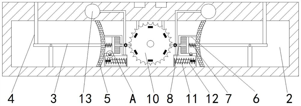
[0027] see Figure 1-6 , an anti-theft alarm self-service vending machine based on the Internet of Things, including a frame 1, a detection chamber 2 is provided at the bottom of the frame 1, a lever 3 is movably connected to the inner bottom of the detection chamber 2, and a vibrating piece is fixedly connected to the top of the lever 3 4. The inside of the detection chamber 2 is fixedly connected with a friction block 5, and the side of the friction block 5 away from the lever 3 is fixedly connected with a temperature box 6, and the inside of the temperature box 6 is fixedly connected with a tension spring 7, which is far away from the side of the friction block 5 One side is fixedly connected with a clamping rod 8, and the side of the clamping rod 8 away from the tension spring 7 is fixedly and movably connected with a claw 9, and the inside of the claw 9 is fixedly connected with a spring, so that only the claws 9 on both sides block the driving wheel at the same time 10, in order to limit the rotation of the driving wheel 10, to ensure better detection effect of the detection mechanism, the inner wall of the detection chamber 2 is fixedly connected with the driving wheel 10, and the front of the driving wheel 10 is fixedly connected with a magnetic block, which is used to drive the cutting block 12 to move. The outer side of 10 is fixed with a bayonet, which is used in conjunction with the claw 9. The inner bottom of the temperature box 6 is fixedly connected with a coil 11, the inside of the coil 11 is slidably connected with a cutting block 12, and the inner top of the detection chamber 2 is fixedly connected with an alarm. 13. The inside of the temperature box 6 is fixedly connected with an electromagnet 14, the inner wall of the temperature box 6 is slidably connected with a top block 15, and the bottom of the top block 15 is fixedly connected with a buffer spring, so that the top block 15 will not delay the movement of the clamping rod 8, only Only when the electromagnet 14 is energized can the movement of the clamping rod 8 be restricted. The inwall of the frame 1 is fixedly connected with a transmission wheel 16, which is connected in transmission with the driving wheel 10, and the inwall of the transmission wheel 16 is slidably connected with a sliding tooth 17. One side away from the crank wheel 18 is fixedly connected with a limit spring to prevent the crank wheel 18 from reversing. The inside of the drive wheel 16 is fixedly connected with a crank wheel 18, and the outside of the crank wheel 18 is fixedly connected with a driving lever, which is used in conjunction with the sliding tooth 17 to prevent The crank wheel 18 rotates, and the inside of the crank wheel 18 is provided with a fan-shaped chute, so that the rotation of the crank wheel 18 becomes the linear motion of the pulley 19. The inside of the crank wheel 18 is slidably connected with a pulley 19, and the top of the pulley 19 is movably connected with a slide bar 20 , the slide bar 20 is slidably connected to the inside of the swing bar 21, so that the swing bar 21 has a larger swing range, the inner wall of the frame 1 is movably connected with the swing bar 21, and the outer sides of the swing bar 21 and the slide bar 20 are fixedly connected with a retaining net, The net is anti-theft, and can prevent sundries. The outside of the drive wheel 16 is engaged with a ratchet 22. The inside of the ratchet 22 is fixedly connected with a reel 23. The outside of the reel 23 is fixedly connected with a retaining net. The ratchet 24 is fixedly connected with a thrust spring on the outside of the ratchet 24, so that the ratchet 22 can rotate relative to the reel 23 without causing the rewinding to block the net.
[0028] Working principle: when the equipment is stolen, the equipment is damaged, the vibrating plate 4 vibrates, the vibrating plate 4 vibrates to drive the lever 3 to swing, the lever 3 swings and rubs against the friction block 5, and the friction block 5 makes the internal temperature of the temperature box 6 rise, and the temperature The mercury inside the box 6 is heated and expands, and the mercury drives the clamping rod 8 away from the driving wheel 10, and the clamping rod 8 drives the claw 9 away from the driving wheel 10. At this time, the driving wheel 10 rotates, and the driving wheel 10 rotates to drive the magnetic block to rotate. When the magnetic block rotates to When approaching the cutting block 12, the cutting block 12 moves to cut the magnetic induction line, so that the coil 11 is energized, and the alarm 13 is alarmed when the coil 11 is energized. The block 15 limits the clamping rod 8, and the drive wheel 10 rotates to drive the transmission wheel 16 to rotate, and the transmission wheel 16 rotates to drive the sliding gear 17 to rotate, and the rotation of the sliding gear 17 drives the crank wheel 18 to rotate through the driving lever, and the crank wheel 18 rotates to drive the pulley 19 moves, the pulley 19 moves to drive the slide bar 20 to swing, the slide bar 20 swings to drive the swing bar 21 to swing, when the swing bar 21 swings to figure 1 The position shown stops swinging, and the swing bar 21 stretches the net, and the net further prevents theft. When the drive wheel 16 rotates, it drives the ratchet 22 to rotate, and the ratchet 22 rotates to drive the ratchet 24 to rotate. Rotate, the reel 23 rotates and unclamps the net, can not interfere with the swing of the fork 21, and now the driving lever drives the sliding tooth 17 to move to the inside of the transmission wheel 16, and the sliding tooth 17 makes the crank wheel 18 not follow the transmission wheel 16 to rotate, and Ensure that the crank wheel 18 will not rotate. When the equipment needs maintenance, the equipment will be powered off, the driving wheel 10 will stop rotating, the coil 11 will be powered off, the alarm 13 will stop alarming, and the clamping lever 8 will reset under the action of the tension spring 7. Drive the claw 9 to reset, at this time, toggle the transmission wheel 16 to reverse, the transmission wheel 16 drives the crank wheel 18 to reverse, the crank wheel 18 reverses to drive the pulley 19 to reset, the pulley 19 drives the pendulum 21 to reset, and the transmission wheel 16 drives the ratchet 22 is reversed, and the ratchet 22 drives the reel 23 to reverse, and the reel 23 collects the retaining net to prevent the retaining net from interfering with the operation of the equipment.
[0029]To sum up, the anti-theft alarm self-service vending machine based on the Internet of Things drives the lever 3 to vibrate through the vibration of the vibrating plate 4, and the friction between the lever 3 and the friction block 5 increases the temperature inside the temperature box 6, and the liquid inside the temperature box 6 pushes the lever 8 moves, the clamp rod 8 drives the claw 9 to move, the claw 9 makes the driving wheel 10 rotate, the driving wheel 10 rotates and drives the cutting block 12 to move through the magnetic block on the front, and the cutting block 12 cuts the magnetic field lines inside the coil 11 to generate electricity , and then through the cooperative use of the coil 11 and the alarm 13, the effect of automatically alarming according to the vibration is achieved. The anti-theft alarm self-service vending machine based on the Internet of Things drives the transmission wheel 16 to rotate through the rotation of the driving wheel 10, the transmission wheel 16 drives the sliding tooth 17 to rotate, the sliding tooth 17 drives the crank wheel 18 to rotate, the crank wheel 18 drives the pulley 19 to move, and the pulley 19 Drive the sliding bar 20 to swing, and then through the cooperation of the sliding bar 20 and the swinging bar 21, the effects of preventing sundries from entering the equipment and facilitating later maintenance are achieved, and the scope of application is wider.
[0030] Although the embodiments of the present invention have been shown and described, those skilled in the art can understand that various changes, modifications and substitutions can be made to these embodiments without departing from the principle and spirit of the present invention. and modifications, the scope of the invention is defined by the appended claims and their equivalents.

PUM

no PUM

Description & Claims & Application Information

We can also present the details of the Description, Claims and Application information to help users get a comprehensive understanding of the technical details of the patent, such as background art, summary of invention, brief description of drawings, description of embodiments, and other original content. On the other hand, users can also determine the specific scope of protection of the technology through the list of claims; as well as understand the changes in the life cycle of the technology with the presentation of the patent timeline. Login to view more.

Similar technology patents

Data isolation interaction method and system based on cloud service

PendingCN112653665AImprove read and write performanceEasy to maintain later
Owner:AEROSPACE INFORMATION

Currency detector for finance

InactiveCN109064623AImprove dustproof levelEasy to maintain later
Owner:杨竣凯

Auxiliary device for directional pickup microphone hanging and user identity confirmation and tracking method

InactiveCN111246324AEase of useEasy to maintain later
Owner:江苏中协智能科技有限公司

Flexible direct current converter transformer

PendingCN114743771Alow costEasy to maintain later
Owner:GUANGZHOU POWER SUPPLY BUREAU GUANGDONG POWER GRID CO LTD

Dual-mode switching method for mobile terminal, adapting device and mobile terminal

ActiveCN101888714AUnified managementEasy to maintain later
Owner:ZTE CORP

Classification and recommendation of technical efficacy words

  • Easy to maintain later

Intelligent express cabinet and intelligent express cabinet control system

PendingCN108734423Areduce product costEasy to maintain later
Owner:PEKING UNIV FOUNDER GRP CO LTD +1

Device and method for monitoring water pressure outside shield tunnel

PendingCN111551307AEasy to installEasy to maintain later
Owner:广东科正水电与建筑工程质量检测有限公司

Magnetic damping device for new energy automobile

InactiveCN110630681AEasy to maintain laterSmooth buffer rebound
Owner:杭州芯意智能科技有限公司

Novel coronavirus sample cup dividing device

PendingCN113150959APut an end to misplacementEasy to maintain later
Owner:深圳美讯医疗科技有限公司

Electric control silicon oil fan clutch

PendingCN109854353AEasy to maintain laterExtended service life
Owner:长春宝成汽车电子有限公司
Why Eureka
Try Eureka