Centrifugal high-speed air compressor for fuel cell, and cooling structure of centrifugal high-speed air compressor

A fuel cell and cooling structure technology, applied in cooling/ventilation devices, electrical components, electromechanical devices, etc., can solve the problems of poor rotor cooling effect, demagnetization of magnetic steel, disadvantage of protecting rotor, etc., so as to improve cooling effect and avoid magnetic steel. The effect of demagnetization

Active Publication Date: 2021-01-22
WENLI GUANGDONG TECH CO LTD
View PDF3 Cites 9 Cited by
  • Summary
  • Abstract
  • Description
  • Claims
  • Application Information

AI Technical Summary

Problems solved by technology

[0002] When the centrifugal high-speed air compressor used for fuel cells increases the output air pressure and flow rate, it will inevitably cause heat dissipation and cooling problems, especially the rotor structure. If the heat dissipation is not handled well, it will cause the demagnetization of the magnetic steel.
[0003] At present, the centrifugal high-speed air compressor for fuel cells uses the exhaust of the volute to cool the rotor in the motor casing, but the temperature of the exhaust of the volute is high, and the cooling effect on the rotor is poor, which is not good for protecting the rotor.

Method used


Image

  • Centrifugal high-speed air compressor for fuel cell, and cooling structure of centrifugal high-speed air compressor
  • Centrifugal high-speed air compressor for fuel cell, and cooling structure of centrifugal high-speed air compressor
  • Centrifugal high-speed air compressor for fuel cell, and cooling structure of centrifugal high-speed air compressor

Examples


Embodiment Construction

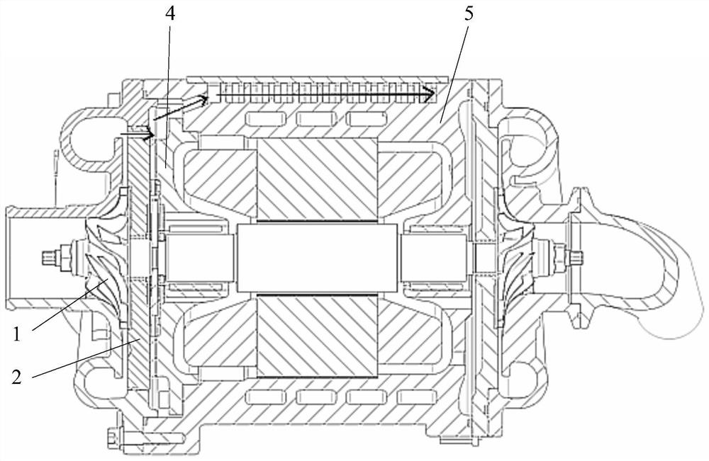
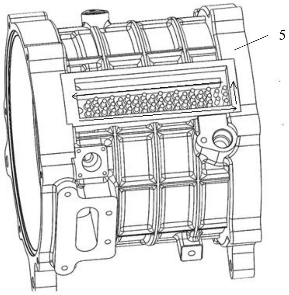
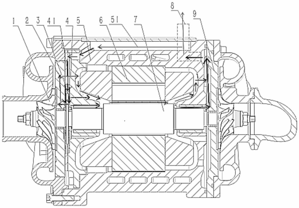
[0023] The embodiment of the present invention discloses a cooling structure of a centrifugal high-speed air compressor for fuel cells, which can draw gas from the volute and transport it to a heat exchanger for pre-cooling with cold water, and then transport the cooled gas to The rotor of the motor is cooled to improve the cooling effect of the cold air on the rotor and avoid demagnetization of the magnetic steel of the rotor. The embodiment of the present invention also discloses a centrifugal high-speed air compressor for a fuel cell, which can improve the reliability of the rotor by applying the cooling structure.

[0024] The following will clearly and completely describe the technical solutions in the embodiments of the present invention with reference to the accompanying drawings in the embodiments of the present invention. Obviously, the described embodiments are only some, not all, embodiments of the present invention. Based on the embodiments of the present invention...


PUM


Abstract

The invention discloses a cooling structure of a centrifugal high-speed air compressor for a fuel cell. The cooling structure comprises an air entraining channel, a heat exchanger and a cooling channel, wherein the heat exchanger is arranged in a motor shell of a centrifugal high-speed air compressor for a fuel cell, and comprises a cold water channel and an air channel which are respectively arranged in the motor shell, the air entraining channel, the air channel and the cooling channel are sequentially communicated, and the air entraining channel conveys airflow in the volute of the centrifugal high-speed air compressor for the fuel cell to the air channel for heat exchange, then conveys the airflow to the cooling channel for cooling the rotor of the centrifugal high-speed air compressorfor the fuel cell, and finally discharges the airflow from an exhaust port formed in the motor shell. According to the cooling structure, gas can be led out of the volute and conveyed to the heat exchanger to be cooled in advance through cold water, and then the cooled gas is conveyed to the rotor of the motor to be cooled, so that the cooling effect of cold air on the rotor is improved, and demagnetization of magnetic steel of the rotor is avoided. The invention further provides the centrifugal high-speed air compressor for the fuel cell.

Description

technical field [0001] The invention relates to the technical field of machinery industry, more specifically, to a cooling structure of a centrifugal high-speed air compressor for a fuel cell, and also to a centrifugal high-speed air compressor for a fuel cell. Background technique [0002] When the centrifugal high-speed air compressor used for fuel cells increases the output air pressure and flow rate, it will inevitably bring about heat dissipation and cooling problems, especially for the rotor structure. If the heat dissipation is not handled properly, the magnetic steel will be demagnetized. [0003] At present, the centrifugal high-speed air compressor for fuel cells uses the exhaust of the volute to cool the rotor in the motor housing, but the temperature of the exhaust of the volute is high, and the cooling effect on the rotor is poor, which is not good for protecting the rotor. [0004] Therefore, how to provide a cooling structure with a better cooling effect on th...

Claims


Application Information

Patent Timeline
Patent Type & Authority Applications(China)
IPC IPC(8): H02K5/20H02K9/04
CPCH02K5/20H02K9/04H02K2205/09Y02E60/50
Inventor 华青松郭志成刘亚波汪晶
Owner WENLI GUANGDONG TECH CO LTD
Why Eureka
Try Eureka