
Sand making machine

A sand making machine and shell technology, which is applied in mechanical equipment, vibration suppression adjustment, grain processing, etc., can solve the problems of incomplete crushing of crushed materials, difficulty in meeting established standards, and damage to components, so as to optimize the effect of impact crushing and prevent The effect of violent shaking and reducing the vibration amplitude

Inactive Publication Date: 2021-01-26
费良芬
View PDF6 Cites 0 Cited by
  • Summary
  • Abstract
  • Description
  • Claims
  • Application Information

AI Technical Summary

Problems solved by technology

[0006] The purpose of the present invention is to solve the problems in the prior art that the single crushing process does not completely crush the crushed materials, it is difficult to meet the established standards, and the vibration causes damage to the components when the device is in operation.

Method used


Image

  • Sand making machine
  • Sand making machine
  • Sand making machine

Examples


Embodiment 1

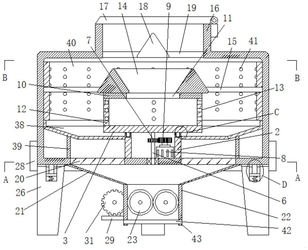
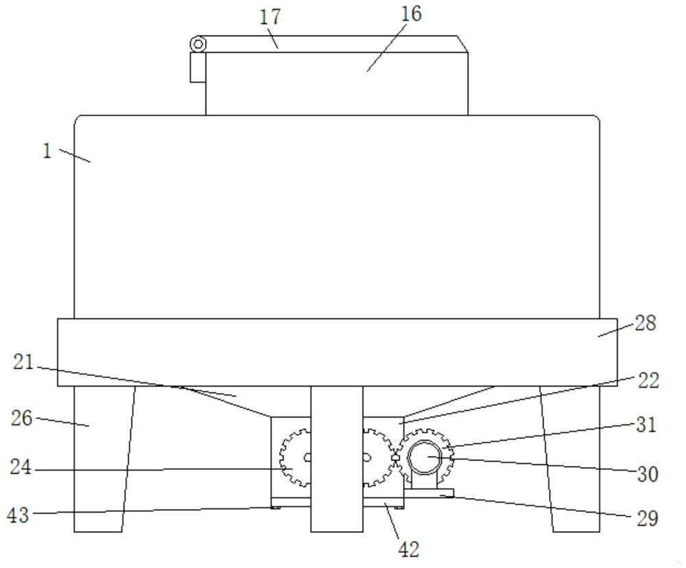
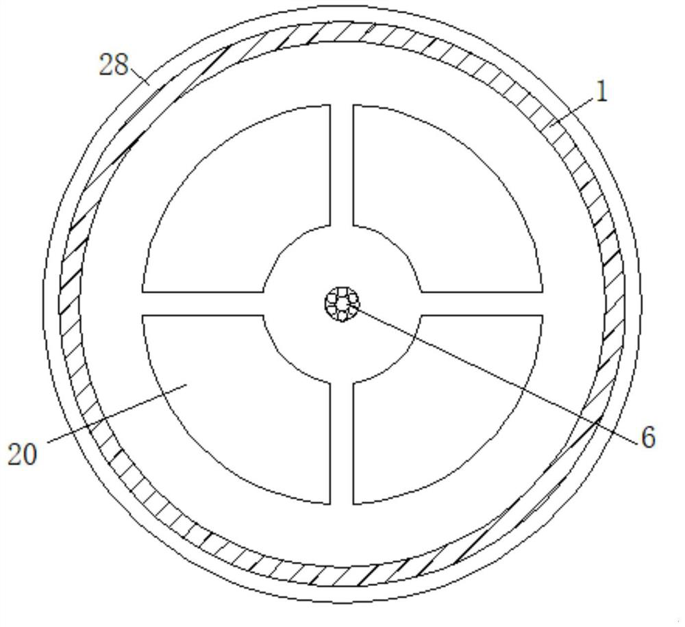
[0033] Embodiment one, such as Figure 1-8As shown, a sand making machine includes a horizontally arranged casing 1, the casing 1 is cylindrical, the inner bottom surface of the casing 1 is fixedly connected with a central cylinder 2, and a first rotating plate 3 is horizontally arranged above the central cylinder 2, The bottom surface of the first rotating plate 3 is fixedly connected with a fixed ring 4, and the upper surface of the central cylinder 2 is provided with a fixed groove 5 that matches the fixed ring 4. The fixed groove 5 is annular, and the fixed ring 4 is rotationally connected with the fixed groove 5. The first The bottom surface of the rotating plate 3 is fixedly connected with a main shaft 6, and the main shaft 6 is vertically arranged. The shaft of the motor 8 is fixedly connected to the second gear 9, and the second gear 9 is meshed with the first gear 7. A second rotating plate 10 is horizontally arranged above the first rotating plate 3, and a circular o...

Embodiment 2

[0034] Embodiment two, such as figure 1 , 2 , 5, the driving mechanism 25 includes a base plate 29 fixedly connected with the tank body 22, the base plate 29 is horizontally arranged, the upper surface of the base plate 29 is fixedly connected with a second motor 30, and the shaft of the second motor 30 is fixedly connected with a driving gear 31. One of the driven gears 24 is meshed with the driving gear 31, and the second motor 30 is used to drive the crushing roller 23 to operate to perform secondary crushing on the crushed materials, so that the crushing effect of the crushed materials is better.

Embodiment 3

[0035] Embodiment three, such as figure 1 , 7 As shown, the shock absorbing mechanism 27 includes a plurality of shock absorbing columns 32 fixedly connected to the outer bottom surface of the casing 1. The plurality of shock absorbing columns 32 are all vertically arranged, and the upper surfaces of the plurality of supporting columns 26 are provided with grooves 33. The bottom end of the shock-absorbing column 32 is fixedly connected with a sliding plate 34, the sliding plate 34 is slidingly connected with the groove 33, the sliding plate 34 is fixedly connected with the inner wall of the groove 33 through a spring 35, and the inner port of the groove 33 is fixedly connected with a limiter 36, The shock-absorbing column 32 is slidingly connected with the stopper 36, the groove 33 is cylindrical, the sliding plate 34 is circular, the stopper 36 is ring-shaped, and the stopper 36 is sleeved on the shock-absorbing column 32 to support The upper surface of the column 26 is fixe...


PUM


Abstract

The invention discloses a sand making machine, which comprises a housing horizontally arranged, wherein the housing is cylindrical; a central cylinder is fixedly connected to the inner bottom surfaceof the housing; a first rotating plate is horizontally arranged above the central cylinder; a fixed ring is fixedly connected to the bottom surface of the first rotating plate; a fixed groove matchedwith the fixed ring is formed in the upper surface of the central cylinder; the fixed groove is annular; the fixed ring is rotationally connected with the fixed groove; the bottom surface of the firstrotating plate is fixedly connected with a main shaft; the main shaft is vertically arranged; the main shaft is rotationally connected with the inner bottom surface of the housing; the main shaft isfixedly connected with a first gear; and one side of the main shaft is provided with a first motor. According to the sand making machine, crushed materials are divided into two parts; one part of thecrushed materials performs centrifugal motion after being accelerated to impact on the other part of the crushed materials, and meanwhile, impacts on a crushing plate to perform primary crushing; andthe crushed materials are subjected to secondary crushing by a crushing roller, so that the crushed materials are crushed more thoroughly; the effect of crushing the crushed materials is better; and the sand making machine is more practical.

Description

technical field [0001] The invention relates to the technical field of stone crushing devices, in particular to a sand making machine. Background technique [0002] Stone crushers can be divided into medical stone crushers and mining stone crushers according to major categories. In principle, mining stone crushers are suitable for crushing a large number of hard rocks in mines. The typical granite output particle size is ≤40mm, accounting for 90%. For materials below 100-500 mm, its compressive strength can reach up to 350 MPa. It has the advantages of large crushing ratio and cubic particles after crushing. Crushing machinery with more than 50% material. [0003] Mining crushers are also called stone crushers, which refer to crushing machines in which the particle size of the discharge is greater than 3mm and accounts for more than 50% of the total discharge volume. It was invented by the British Hengan. The crushing operation is often based on the size of the feed and dis...

Claims


Application Information

Patent Timeline
IPC IPC(8): B02C4/02B02C4/28B02C4/42B02C21/00B02C23/00B02C23/02B02C19/00F16F15/067
CPCB02C4/02B02C4/28B02C4/42B02C19/005B02C21/00B02C23/00B02C23/02F16F15/067
Inventor 费良芬王明宇刘东祥
Owner 费良芬
Learn More