
A CNC tool intelligent tool setting monitoring method

A kind of cutting tool and intelligent technology, applied in the direction of manufacturing tools, automatic control devices, metal processing machinery parts, etc., can solve the problems of high operator skill requirements, troublesome debugging, high price, etc., to eliminate the loss of quality cost and reduce tool setting time. , the effect of convenient operation

Active Publication Date: 2022-06-24
内江金鸿曲轴有限公司
View PDF10 Cites 0 Cited by
  • Summary
  • Abstract
  • Description
  • Claims
  • Application Information

AI Technical Summary

Problems solved by technology

[0002] When changing the tool of the CNC machining center, it is necessary to manually rotate the tool coordinates to the zero point of the processed product, and then manually input the data for tool setting (commonly known as manual tool setting). Accidents such as accidents often occur, and the cost of products, tools, tooling, and equipment is greatly lost, and at the same time, the requirements for the operator's skills are relatively high.
[0003] The tool setting instrument is used to improve the auxiliary time such as tool adjustment during workpiece processing. Now because the machine tool does not have tool breakage and wear detection function, when the tool is worn or broken or broken during processing, the operator cannot find it in time, resulting in product scrapping, associated tool scrapping, Risks such as machine collisions, tooling collisions, and outflow of defective products often appear, especially in digital, intelligent, fully automatic unmanned production lines and rack manipulator lines.
[0004] At present, some imported equipment comes with a tool setting detection system, but debugging is troublesome and the price is very expensive. When changing tools or product models, it is necessary to re-learn, adjust and monitor the position of the import and export, and a large number of product processing verifications are required to determine the final life of the tool. Alarm line debugging

Method used

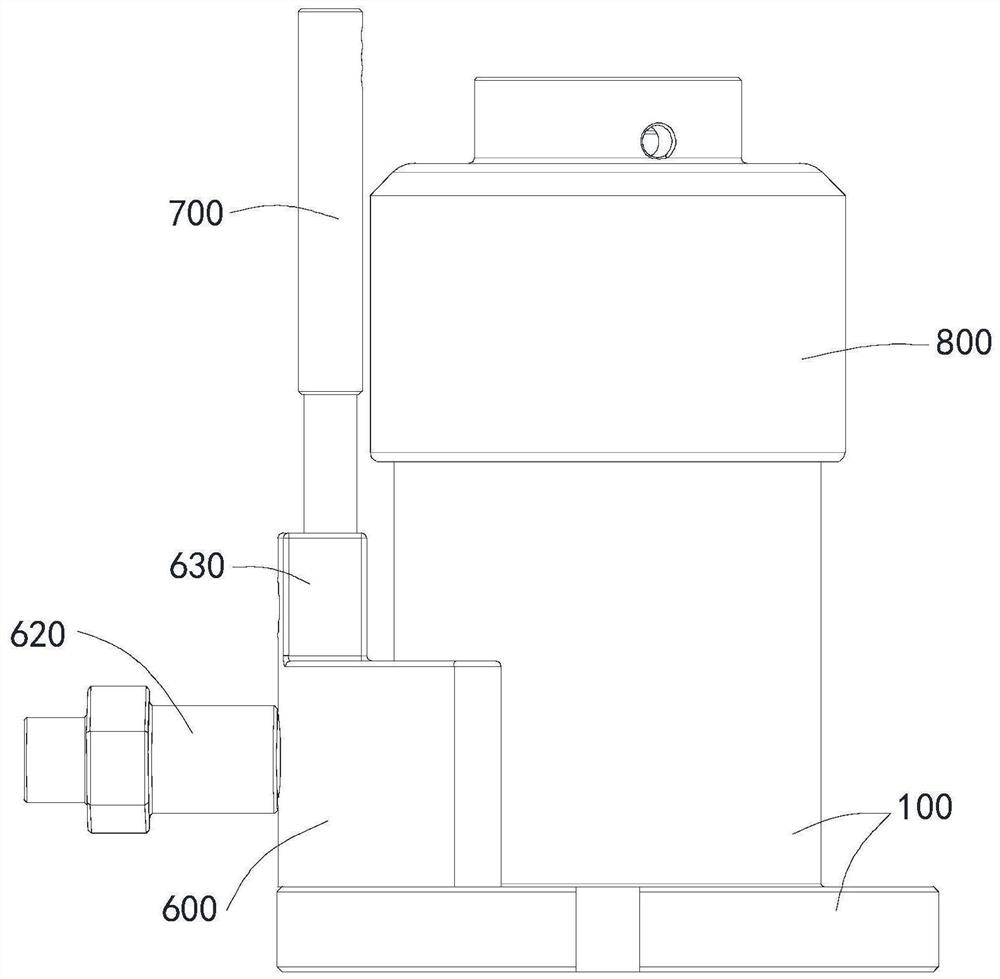
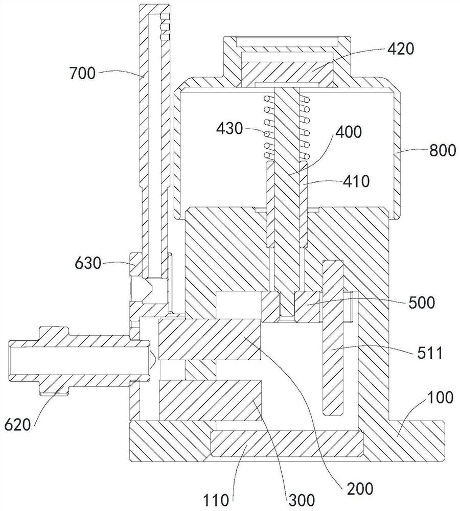
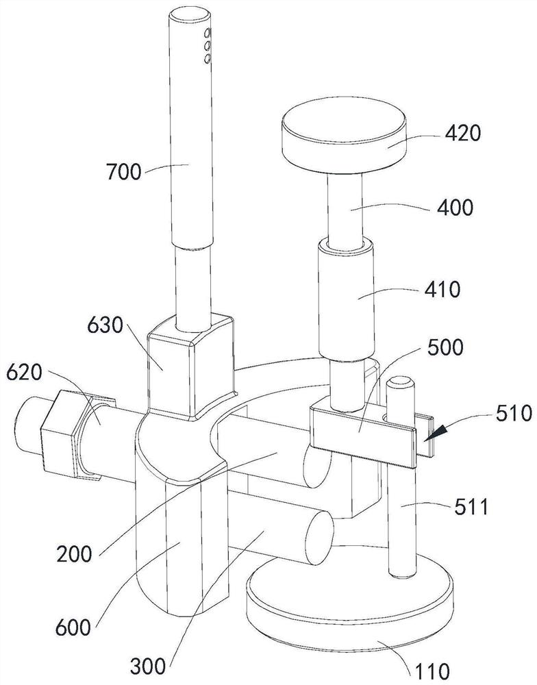

Image

  • A CNC tool intelligent tool setting monitoring method
  • A CNC tool intelligent tool setting monitoring method
  • A CNC tool intelligent tool setting monitoring method

Examples


Embodiment Construction

[0041] In order to make the purposes, technical solutions and advantages of the embodiments of the present invention clearer, the technical solutions in the embodiments of the present invention will be clearly and completely described below with reference to the accompanying drawings in the embodiments of the present invention. Obviously, the described embodiments These are some embodiments of the present invention, but not all embodiments. The components of the embodiments of the invention generally described and illustrated in the drawings herein may be arranged and designed in a variety of different configurations.

[0042] Thus, the following detailed description of the embodiments of the invention provided in the accompanying drawings is not intended to limit the scope of the invention as claimed, but is merely representative of selected embodiments of the invention. Based on the embodiments of the present invention, all other embodiments obtained by those of ordinary ski...


PUM


Abstract

A CNC tool intelligent tool setting monitoring method, including step S1 - type change operation and step S2 - automatic tool setting, wherein step S1 involves installing a fixed tool setting instrument, setting the coordinates of the tool setting instrument, tool setting axis tool setting and program Setting, step S2 includes step S2.1 - replace the tool and install it on the spindle, select the tool setting switch parameter in the macro parameter and change it to 1, step S2.2 - select the tool to be set, and set the corresponding macro parameter Change it to 1 to complete the tool setting operation, step S2.3 - press the cycle start button of the processing program. The system is easy to debug. When changing the model, you only need to find the difference between the workpiece and the tool setting instrument. The macro program is used to judge the mechanical coordinates. For CNC machining parts, automatic tool setting, automatic tool compensation, and tool wear detection can be realized when the tool is changed. , Tool damage and fracture detection, to eliminate the loss of quality cost caused by tool errors, reduce the time for tool setting of parts, and easy to operate.

Description

technical field [0001] The invention relates to the technical field of CNC machine tool processing, in particular to a method for monitoring intelligent tool setting of CNC tools. Background technique [0002] When changing the tool of the CNC machining center, it is necessary to manually shake the tool coordinate with the handwheel to the zero point of the processed product, and then manually input the data for tool setting (commonly known as manual tool setting). Accidents such as these often occur, and the cost of products, tools, tooling and equipment is relatively large, and at the same time, the skills of operators are relatively high. [0003] The tool setter is used to improve the auxiliary time such as tool adjustment during workpiece processing. Since the machine tool has no tool breakage and wear detection function, when the tool wears out or is damaged or broken during the machining process, the operator cannot find it in time, resulting in scrapped products, scr...

Claims


Application Information

Patent Timeline
Patent Type & Authority Patents(China)
IPC IPC(8): B23Q15/22B23Q15/28B23Q17/09
CPCB23Q15/22B23Q15/28B23Q17/0909B23Q17/0904
Inventor 赵小东兰燕
Owner 内江金鸿曲轴有限公司
Learn More