Wood board uniform cutting equipment for building materials
A technology for cutting equipment and boards, which is applied in wood processing equipment, special forming/shaping machines, manufacturing tools, etc., and can solve the problems of low cutting efficiency, uneven cutting, and high labor intensity of wood boards
- Summary
- Abstract
- Description
- Claims
- Application Information
AI Technical Summary
Problems solved by technology
Method used
Image

Examples
Embodiment 1
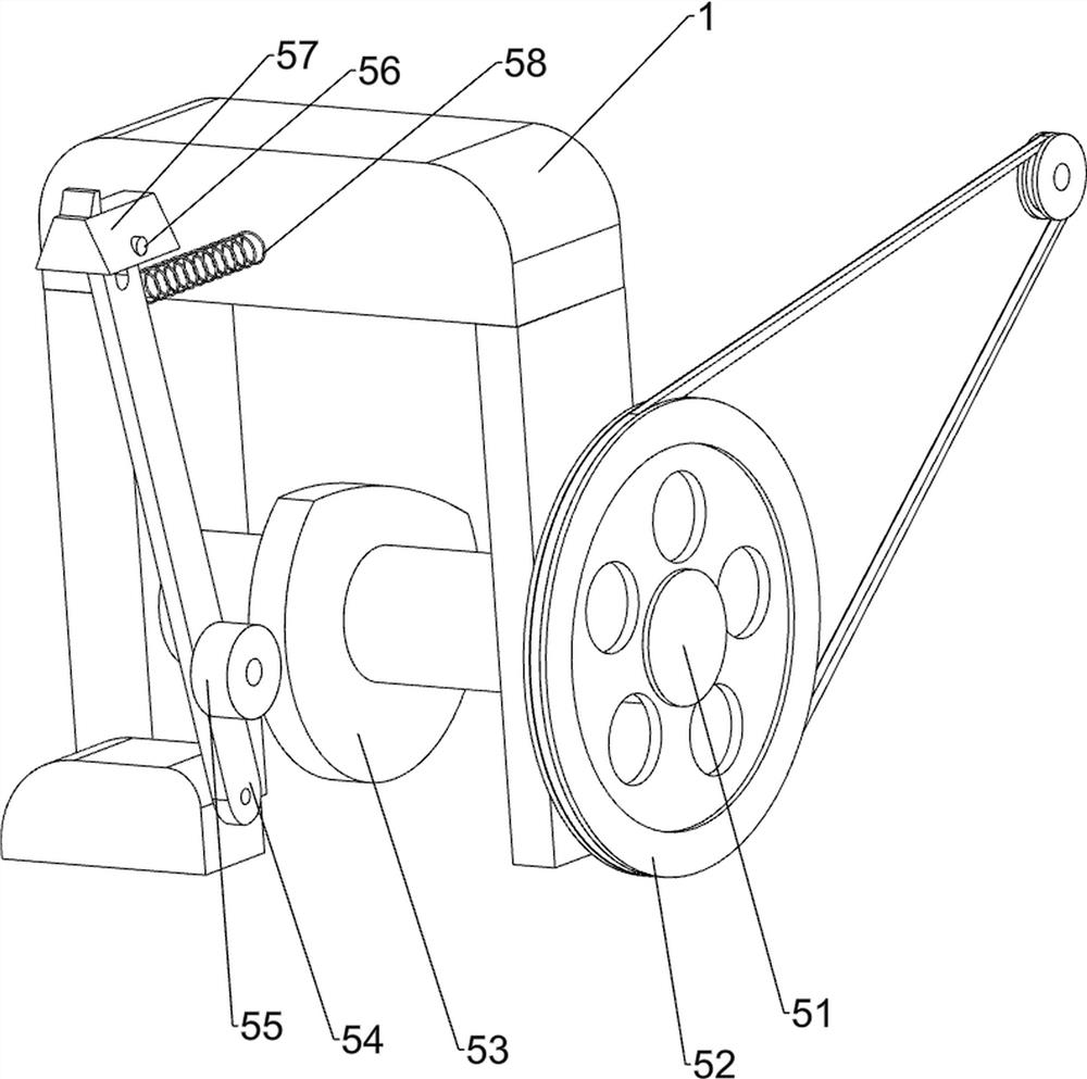
[0028] A kind of equipment for uniform cutting of wooden boards for building materials, such as figure 1 As shown, it includes a mounting plate 1, a servo motor 2, a transmission mechanism 3, an extrusion mechanism 4, a feeding mechanism 5, an adjusting mechanism 6 and a cutting mechanism 7. 1 is provided with a transmission mechanism 3 on the rear side of the upper part, and the transmission mechanism 3 is connected with the servo motor 2; There is a feeding mechanism 5 at the bottom, and the feeding mechanism 5 is connected with the transmission mechanism 3. An adjustment mechanism 6 is arranged on the left side of the upper rear part of the installation plate 1, and a cutting mechanism 7 is arranged on the upper rear side of the installation plate 1. The cutting mechanism 7 and the adjustment mechanism 6 Connected, the cutting mechanism 7 is connected with the output shaft of the servo motor 2.
[0029] First, people stack multiple pieces of wood boards to be cut on the fr...
Embodiment 2
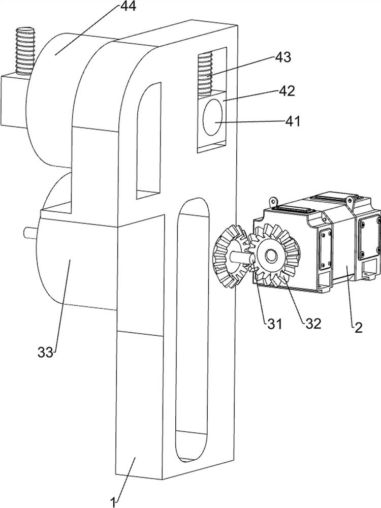
[0031] On the basis of Example 1, such as figure 2 , image 3 , Figure 4 and Figure 5 As shown, the transmission mechanism 3 includes a first rotating shaft 31, a bevel gear set 32 and a first roller 33, and the first rotating shaft 31 is rotationally connected between the left and right sides of the upper rear part of the mounting plate 1, and the right side of the first rotating shaft 31 is connected to the A bevel gear set 32 is arranged between the front sides of the output shafts of the servo motor 2 , and a first roller 33 is arranged in the middle of the first rotating shaft 31 .
[0032] The rotation of the output shaft of the servo motor 2 drives the bevel gear set 32 to rotate, thereby driving the first rotating shaft 31 to rotate, and then driving the first roller 33 to rotate, so that the planks passing above the first roller 33 can be transmitted backwards.
[0033] The extruding mechanism 4 includes a second rotating shaft 41, a first slide block 42, ...
Embodiment 3
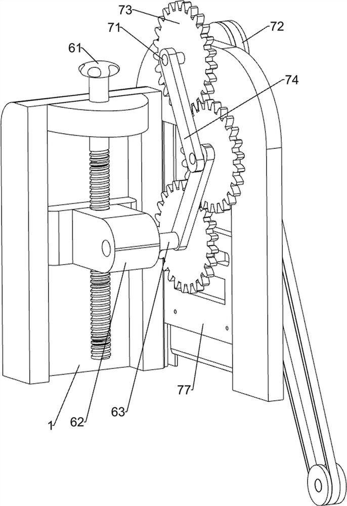
[0042] On the basis of Example 2, such as figure 1 and Figure 6 As shown, a fixing mechanism 8 is also included. The upper rear portion of the mounting plate 1 and the bottom of the cutting tool 77 are provided with a fixing mechanism 8. The fixing mechanism 8 includes a second elastic member 81, a fifth slide block 82, a third elastic member 83 and Fixed plate 84, the left and right sides of the upper rear part of mounting plate 1 are all provided with second elastic member 81, and cutting tool 77 bottom front sides are provided with the 5th slide block 82, and the 5th slide block 82 bottom rear sides are all connected with the 5th slide block 82 on both sides. The two elastic pieces 81 are connected, and the left and right sides of the lower end of the fifth slider 82 are provided with a third elastic piece 83 , and a fixing plate 84 is connected between the two third elastic pieces 83 .
[0043] The cutting tool 77 moves downwards to drive the fifth slider 82 to move down...
PUM
 Abstract
Description
Claims
Application Information
 - R&D
- Intellectual Property
- Life Sciences
- Materials
- Tech Scout
- Unparalleled Data Quality
- Higher Quality Content
- 60% Fewer Hallucinations
Browse by: Latest US Patents, China's latest patents, Technical Efficacy Thesaurus, Application Domain, Technology Topic, Popular Technical Reports.
© 2025 PatSnap. All rights reserved.Legal|Privacy policy|Modern Slavery Act Transparency Statement|Sitemap|About US| Contact US: help@patsnap.com