Mounting and fixing box for BMS new energy battery

A new energy and fixed box technology, applied in the direction of batteries, secondary batteries, battery pack components, etc., can solve the problems of affecting the service life, easy to shake batteries, damage, etc., and achieve the effect of efficient heat dissipation and convenient transfer

Pending Publication Date: 2021-03-23
南京金邦动力科技有限公司
View PDF6 Cites 3 Cited by
  • Summary
  • Abstract
  • Description
  • Claims
  • Application Information

AI Technical Summary

Problems solved by technology

[0005] Aiming at the deficiencies of the prior art, the present invention provides a BMS new energy battery installation and fixing box, which solves the problem that the battery is easily shaken inside the battery box, causing damage to the battery and affecting the service life.

Method used


Image

  • Mounting and fixing box for BMS new energy battery
  • Mounting and fixing box for BMS new energy battery
  • Mounting and fixing box for BMS new energy battery

Examples


Embodiment 1

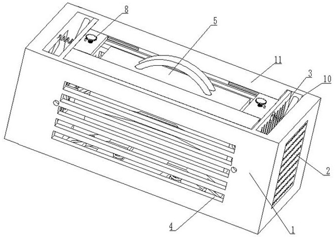
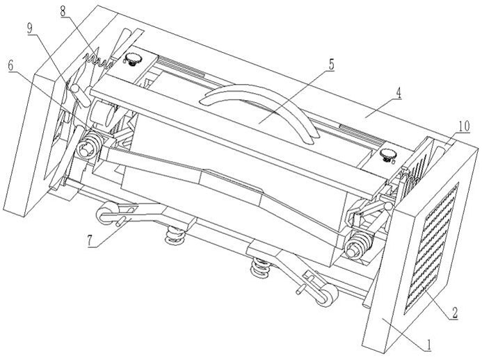
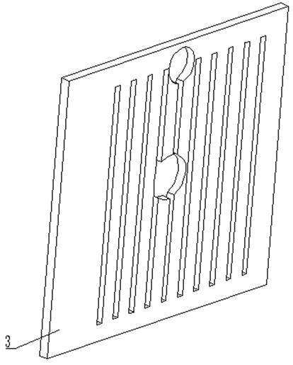
[0033] see Figure 1-5 , a BMS new energy battery installation and fixing box, including a chassis 1, a filter screen 2 is fixedly installed on both sides of the chassis 1, the front and rear of the chassis 1 are provided with ventilation grooves 4, and the inside of the chassis 1 is provided with The device slot 10, the inner wall of the device slot 10 is fixedly connected with the heat dissipation plate 3, the inside of the cabinet 1 is provided with a battery body 5, the upper surface of the cabinet 1 is welded with a fixing plate 11, and the inside of the fixing plate 11 is provided with a fixing mechanism 8, the cabinet 1 A buffer mechanism 6 is provided inside the case 1, a moving mechanism 7 is provided at the bottom of the case 1, and a heat dissipation device 9 is provided at the bottom of the case 1.

[0034] In this embodiment, the buffer mechanism 6 includes a fixed slide bar 61, the surface of the fixed slide bar 61 is slidably connected with two slide plates 63, ...

Embodiment 2

[0040] see Figure 6-7 , the fixing mechanism 8 includes a sliding support plate 85, the bottom of the sliding support plate 85 is welded with a connecting plate 84, the right side of the connecting plate 84 is welded with a cover spring 81, and the right end of the cover spring 81 passes through the cooling plate 3 and is connected to the chassis 1 is fixedly connected to the inner wall, the surface of the fixed plate 11 is provided with a chute 87, the surface of the sliding support plate 85 is slidably connected to the inner wall of the chute 87, and the connecting plate 84 will be pushed by the cover spring 81, and the connecting plate 84 will be Push the sliding support plate 85 to slide inward, which will drive the pressing block 83 to press on the upper surface of the battery, so as to realize the overall automatic fixing effect of the battery, so that the battery will not fall and slide out inside the chassis 1, and improve the stability of the battery. stability.

[...


PUM


Abstract

The invention relates to the technical field of new energy batteries, and discloses a mounting and fixing box for a BMS new energy battery. The mounting and fixing box comprises a case, and is characterized in that filter screens are fixedly mounted on the two sides of the case, vent grooves are formed in the front portion and the rear portion of the case, a device groove is formed in the case, aheat dissipation plate is fixedly connected to the inner wall of the device groove, a fixing mechanism is arranged in the fixing plate, a buffer mechanism is arranged in the case, a moving mechanism is arranged at the bottom of the case, and a heat dissipation device is arranged at the bottom of the case. According to the mounting and fixing box for the BMS new energy battery, the battery body isput in from the opening part of the upper surface of the case, a side pressing frame is extruded inwards through the elastic force of a first spring and a second spring, two connecting rods are crossed at the same time to achieve supporting and clamping effects on the battery, and meanwhile, enough elastic force is provided to reduce the buffer force on the battery, so that the battery is better protected from being damaged.

Description

technical field [0001] The invention relates to the technical field of new energy batteries, in particular to a BMS new energy battery installation and fixing box. Background technique [0002] The power battery is the power source that provides the power source for the tool, and mostly refers to the battery that provides power for electric vehicles, electric trains, electric bicycles, and golf carts. It is mainly different from the starter battery used to start the car engine. Valve-port sealed lead-acid batteries, open tubular lead-acid batteries and lithium iron phosphate batteries are mostly used [0003] At present, many new energy batteries are used to install the battery inside the battery box, and in the process of moving or shaking the device, it is easy to cause damage to the inside of the battery and affect the service life of the battery. Some batteries The equipment in the box is relatively large, and it is very troublesome in the process of transportation. Th...

Claims


Application Information

Patent Timeline
Patent Type & Authority Applications(China)
IPC IPC(8): H01M50/242H01M50/244H01M50/249H01M50/264H01M50/256H01M10/613H01M10/625H01M10/6563
CPCH01M10/613H01M10/625H01M10/6563H01M2220/20Y02E60/10
Inventor 田伟
Owner 南京金邦动力科技有限公司
Why Eureka
Try Eureka