
Secondary ejection mechanism for motor housing mold

A technology of secondary ejection and cover, which is applied to household appliances, other household appliances, applications, etc., can solve problems such as low production efficiency and inability to achieve fully automated production.

Pending Publication Date: 2021-01-26
NINGBO FANGZHENG TOOL
View PDF5 Cites 1 Cited by
  • Summary
  • Abstract
  • Description
  • Claims
  • Application Information

AI Technical Summary

Problems solved by technology

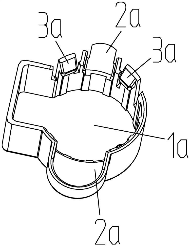
Due to the existence of the barb 3a, if the straight ejection mechanism is designed as the ejection mechanism, it is necessary to manually remove the barb 3a after the product is ejected, and the production efficiency is very low
If the inclined ejector mechanism is designed as the ejector mechanism, the product will be ejected at one time, and sometimes the barb 3a will hang on the inclined ejector, so manual inspection is still required, which belongs to semi-automatic production. Although it is improved compared with the straight ejector mechanism, However, it is still not possible to realize fully automated production

Method used


Image

  • Secondary ejection mechanism for motor housing mold
  • Secondary ejection mechanism for motor housing mold
  • Secondary ejection mechanism for motor housing mold

Examples


Embodiment

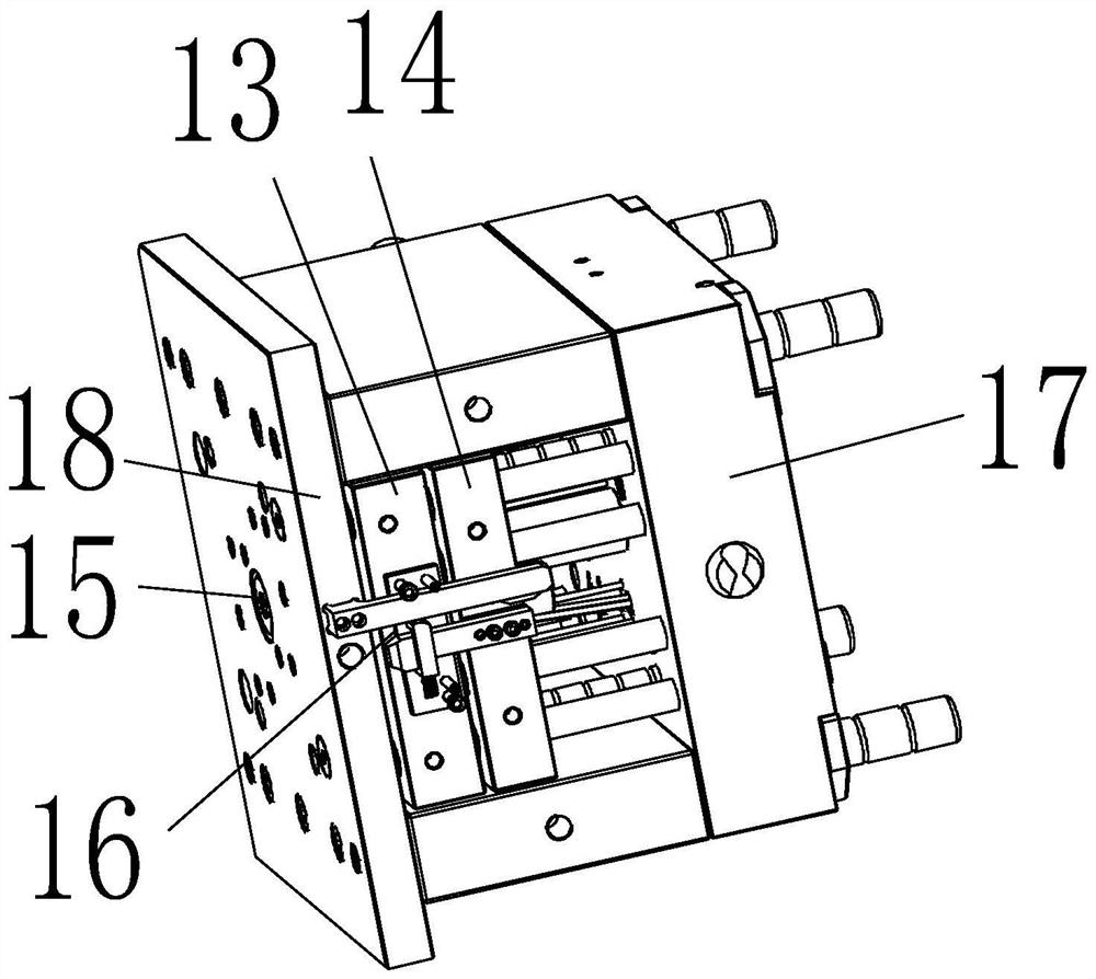
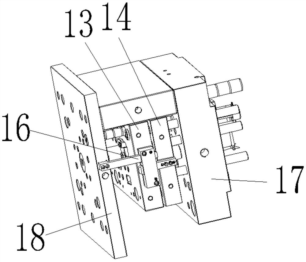
[0033]A secondary ejection mechanism for a motor housing mold, comprising a mold base 1, the front side of the mold base 1 is a product forming side 2, and several mold cores 3 are arranged on the product forming side 2, and the mold The cores 3 are arranged in two rows, and runners 4 are arranged between the two rows of mold cores 3, and the first straight top mechanism, the second straight top mechanism, the third straight top mechanism, and the Inclined jacking mechanism, the first straight jacking mechanism includes at least two first straight jacking pins 5, the second straight jacking mechanism includes at least two second straight jacking pins 6, and the third straight jacking mechanism includes at least two first straight jacking pins 5. Three straight ejector pins 7, the inclined ejector mechanism includes at least two inclined ejector pins 8, one end of the first straight ejector pin 5 protrudes into the first positioning groove 9 of the inner bottom surface of the pr...


PUM


Abstract

The invention discloses a secondary ejection mechanism for a motor housing mold. The ejection mechanism comprises a mold frame, the front side of the mold frame is a product forming side, a pluralityof mold cores are arranged on the product forming side, and the secondary ejection mechanism is characterized by further comprising a first straight ejection mechanism, a second straight ejection mechanism, a third straight ejection mechanism and an inclined ejection mechanism which are arranged behind the mold cores; the first straight ejection mechanism comprises at least two first straight ejection pins, the second straight ejection mechanism comprises at least two second straight ejection pins, the third straight ejection mechanism comprises at least two third straight ejection pins, the inclined ejection mechanism comprises at least two inclined ejection pins, one end of each first straight ejection pin penetrates through the mold cores and then extends into a first positioning groovein the bottom face of the inner side of a product main body in a protruding mode, one end of each second straight ejection pin penetrates through the mold cores and then extends into a second positioning groove in a lug part of a product in a protruding mode, and one end of each third straight ejection pin penetrates through the product forming side and then abuts against a coagulated material ina runner. According to the mechanism, barbs cannot be hung on the inclined injection mechanisms, manual operation is not needed, and therefore full-automatic production can be achieved.

Description

technical field [0001] The invention relates to the technical field of moulds, in particular to a secondary ejection mechanism for motor housing moulds. Background technique [0002] An existing motor casing has a structure such as figure 1 As shown, it includes a main body 1a with an internal depression, and two ear portions 2a arranged on both sides of the main body 1a, and barbs 3a are also provided on the inner side wall of the main body 1a. Due to the presence of the barb 3a, if a straight ejection mechanism is designed as the ejection mechanism, it is necessary to manually remove the barb 3a after the product is ejected, and the production efficiency is very low. If the inclined ejector mechanism is designed as the ejector mechanism, the product will be ejected at one time, and sometimes the barb 3a will hang on the inclined ejector, so manual inspection is still required, which belongs to semi-automatic production. Although it is improved compared with the straight e...

Claims


Application Information

Patent Timeline
IPC IPC(8): B29C45/44B29L31/34
CPCB29C45/44B29L2031/34
Inventor 彭佩金伟俞方敏王一栋徐利永李恒青王正亮王晓锋华祥通
Owner NINGBO FANGZHENG TOOL
Learn More