a multifunctional rod

一种多功能、组合结构的技术,应用在多功能杆领域,能够解决耗材等问题

Active Publication Date: 2022-06-03
ZHEJIANG JINGRI LIGHTING TECH
View PDF7 Cites 1 Cited by
  • Summary
  • Abstract
  • Description
  • Claims
  • Application Information

AI Technical Summary

Problems solved by technology

Although the hollow part is designed, in order to ensure the stability of the groove, the thickness of the light pole at the bottom of the groove must be sufficient, and in order to ensure the stability of the groove, the distance between the groove wall and the hollow part etc. must also have a certain thickness, so in order to ensure the stability of the structure, it is necessary to strengthen the structure of the entire rod body.

Method used


Image

  • a multifunctional rod
  • a multifunctional rod
  • a multifunctional rod

Examples


Embodiment 1

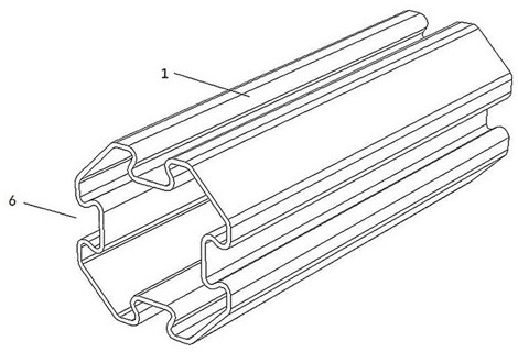
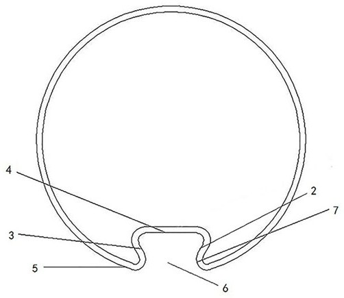
[0035] This embodiment provides a multifunctional rod 1, which is mainly used to improve the stability of the structure while saving materials. The multifunctional rod 1 includes: a first locking wall 2, a second locking wall 3, a connecting wall 4 and a supporting wall 5; the bottoms of the first locking wall 2 and the second locking wall 3 are connected by the connecting wall 4, In addition, the first locking wall 2 and the second locking wall 3 are gradually approached outward from the connecting wall 4 to form an installation opening 6 at their ends; the supporting walls 5 are arranged on both sides of the installation opening 6 and the side corresponding to the installation opening 6 There is a buffer angle 7 between the supporting wall 5 and the correspondingly connected locking wall.

[0036] In this embodiment, as figure 2, both the first locking wall 2 and the second locking wall 3 are folded towards the interior of the multi-function rod 1 along one end of the conn...

Embodiment 2

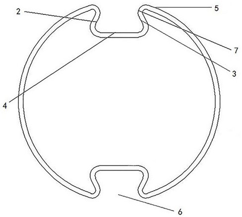
[0047] In this embodiment, different from the single installation port 6 in the first embodiment, the multi-function pole 1 contains multiple installation ports. Due to the development of the 5G era, multiple devices need to be installed on the multi-function pole 1. The structure of a single installation port 6 is not enough to meet the requirements for high installation of external equipment, so the number of installation ports 6 can be determined according to different environments, the number of installation equipment and the direction of installation of the equipment. Secondly, if multiple external devices need to be installed, the multi-function rod 1 with a single installation port 6 can only be installed on the side of the multi-function rod 1 containing the installation port 6, which is easy to be affected by the pulling force of the external equipment received at the installation port 6. Multifunctional pole 1 for stability. In order to ensure the stability of the mu...

Embodiment 3

[0049] The difference between this embodiment and the above-mentioned first and second embodiments is that: Image 6 , the support wall 5 includes a flat support part 5-1, the flat support part 5-1 is arranged close to the installation port 6, and is connected with the locking wall on the corresponding side of the installation port 6; the flat support of the support arms on both sides of the same installation port 6 The parts 5-1 are located in the same plane. On the one hand, one end of the flat support portion 5-1 on both sides of the installation port 6 is connected to the corresponding locking wall to strengthen the locking wall, and the other end forms a certain angle with other parts of the support wall 5. The included angle is the same as the buffer angle in the first embodiment, and acts as a buffer for the force received by the flat support portion 5-1. On the other hand, the flat supports 5-1 on both sides of the mounting opening 6 are in the same plane. When insta...


PUM


Abstract

The invention belongs to the technical field of lighting machinery technology, and specifically relates to a multifunctional rod, which is mainly used for improving the stability of the structure while saving materials. The present invention comprises: a first locking wall, a second locking wall, a connecting wall and a supporting wall; the bottoms of the first locking wall and the second locking wall are connected through the connecting wall, and the first The locking wall and the second locking wall gradually approach outwards from the connecting wall to form an installation opening at their ends; the supporting wall is arranged on both sides of the installation opening and is locked on the corresponding side of the installation opening The wall is connected, and there is a buffer angle between the supporting wall and the correspondingly connected locking wall. The invention reduces the step of slotting on the multifunctional rod, solves the problem of using more materials due to slotting on the side wall of the multifunctional rod, and ensures that the structure can strengthen the stability of the structure while reducing the use of materials.

Description

technical field [0001] The invention belongs to the technical field of lighting machinery technology, in particular to a multifunctional rod, which is mainly used for improving the stability of the structure while saving materials. Background technique [0002] With the advent of the 5G era, smart light poles have become the foundation of 5G construction. The signals emitted by 5G base stations installed on light poles can cover every part of the city, allowing everyone to feel the wisdom brought by 5G. Therefore, in the 5G era, smart street lights are an indispensable part, and smart street lights have become a field of attention in urban construction in recent years. In addition to the installation of 5G base stations, monitoring, environmental monitoring, audio, and face recognition can also be installed. Devices such as installations have realized the multi-purpose skill of a light pole and promoted the process of smart cities. For example, for a portable street light p...

Claims


Application Information

Patent Timeline
Patent Type & Authority Patents(China)
IPC IPC(8): F21S8/08E04H12/00E04H12/08
CPCE04H12/00E04H12/08E04H12/085Y02B20/72
Inventor 程世友姚斌斌潘佳欢叶少军汤燕军
Owner ZHEJIANG JINGRI LIGHTING TECH
Why Eureka
Try Eureka