Standing type high-voltage cable operation device

A working device, high-voltage cable technology, applied in overhead lines/cable equipment, climate change adaptation, etc., can solve problems such as missing parts, broken strands, and large cable creeping force

Active Publication Date: 2021-01-26
LANGFANG POWER SUPPLY COMPANY STATE GRID JIBEI ELECTRIC POWER COMPANY +1
View PDF7 Cites 0 Cited by
  • Summary
  • Abstract
  • Description
  • Claims
  • Application Information

AI Technical Summary

Problems solved by technology

[0002] It is well known that high-voltage or ultra-high-voltage lines are the main way of long-distance electric energy transmission, and high-voltage cables are bridges between power supply equipment and electric equipment, and play the role of transmitting electric energy; they are widely used, so failures often occur, and the high-voltage cables used The cables are bare wires. During long-term use, the spacers on the high-voltage cables are "roughly divided into one-shaped, Y-shaped, X-shaped, wooden-shaped or rice-shaped according to the number of lines", and parts are prone to missing parts due to long-term wind force, so Regular maintenance is required; high-voltage cables in heavy ice areas are affected by de-icing operations, which will also cause strand breakage problems; and there are many cases of high-voltage cable system failures caused by high-voltage cables due to construction quality, such as cables on the surface of the line during construction. It is inevitable that small slip marks will be left, and high-voltage cables exposed to the air and affected by acid rain will leave hidden dangers for long-term safe operation; A small number of broken strands; the above faults should be eliminated in time; most of the current maintenance or repairs use a safety belt, and then people stand on the lower high-voltage cable to complete the work, which is not only very inconvenient, but also extremely difficult

Method used


Image

  • Standing type high-voltage cable operation device
  • Standing type high-voltage cable operation device
  • Standing type high-voltage cable operation device

Examples


Embodiment Construction

[0026] The present invention is further described below in conjunction with embodiment; The following embodiment is not for the limitation of the present invention, only as the mode of supporting the realization of the present invention, any equivalent structural replacement within the technical framework disclosed in the present invention, all is the present invention. the scope of protection of the invention;

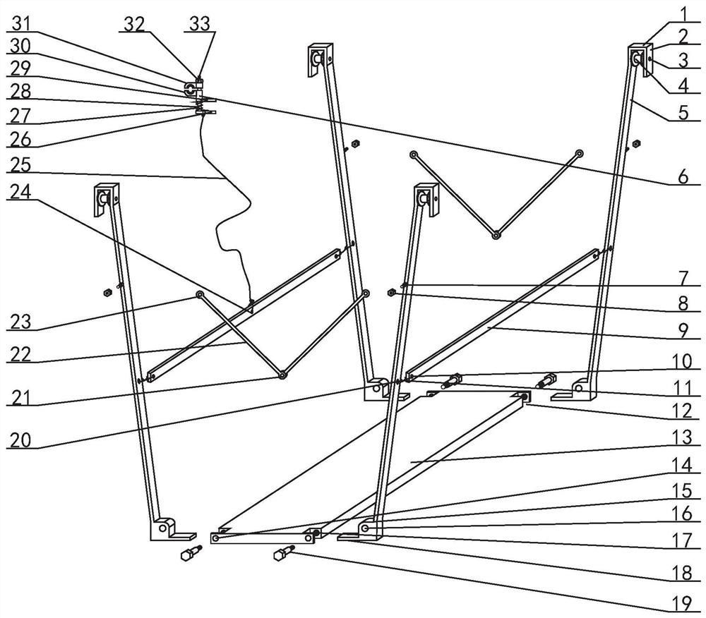
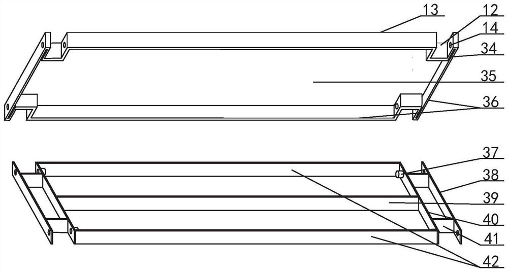
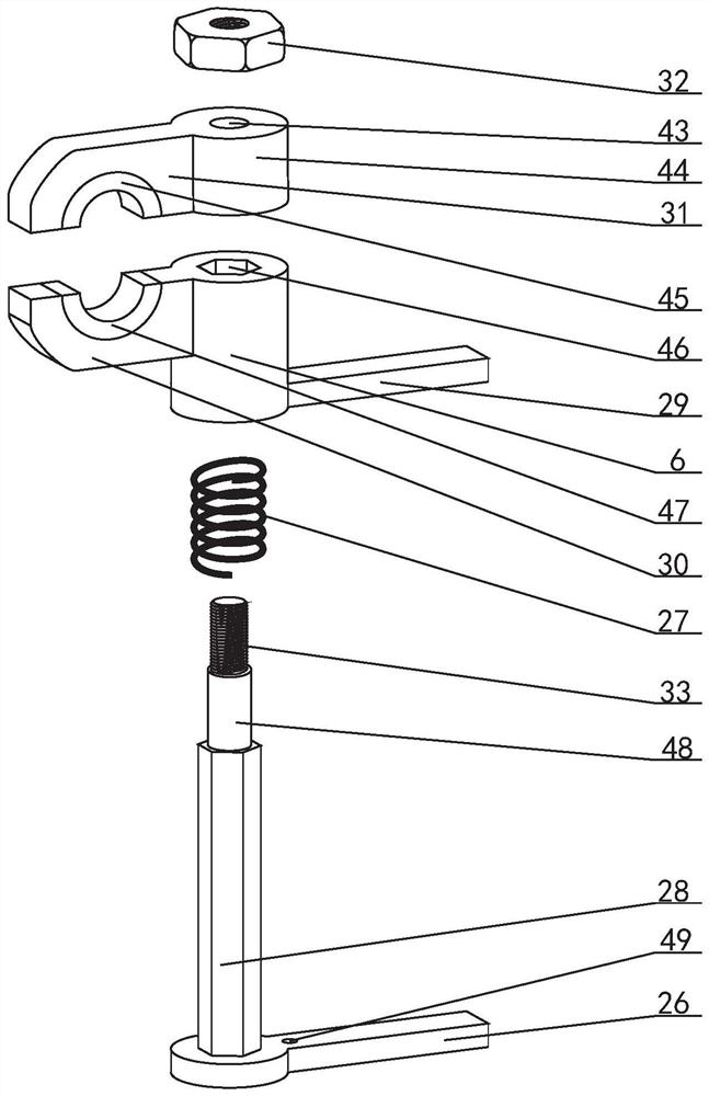
[0027] combined with Figure 1-7 The standing high-voltage cable working device described in includes a standing board 13, a vertical rod 5, a sheave 4, a telescopic rod 22, a retaining rod 9 and a cable lock device, and the two sides of the standing board 13 are respectively connected with four vertical rods near the front and rear ends. The lower ends of the 5 are hingedly connected, and sheaves 4 are respectively arranged on the outer sides of the upper ends of the four vertical rods 5, and telescopic rods 22 are respectively arranged between the vertical rods 5 on...


PUM


Abstract

The invention discloses a standing type high-voltage cable operation device and relates to a high-voltage cable maintenance device. Two sides of a standing plate (13) are respectively hinged with thelower ends of four vertical rods (5) close to the front end and the rear end, grooved wheels (4) are respectively arranged on the outer sides of the upper ends of the four vertical rods, and telescopic rods (22) are respectively arranged between the vertical rods on two sides of the front part of the standing plate and the rear part; a stop lever (9) is arranged between the middles of every two vertical rods on the two sides of the standing plate respectively, and the cable locking device is connected with any vertical rod or any stop lever or any telescopic rod through a pull rope (25). According to the invention, the four vertical rods arranged on the standing plate are respectively hung on a high-voltage cable, and the high-voltage cable is braked by the cable locking device, so stableoperation maintenance on the high-voltage cable is obtained.

Description

【Technical field】 [0001] The invention relates to a high-voltage cable maintenance device, in particular the invention relates to a standing high-voltage cable operation device. 【Background technique】 [0002] It is well known that high-voltage or ultra-high-voltage lines are the main way of long-distance electric energy transmission, and high-voltage cables are bridges between power supply equipment and electric equipment, and play the role of transmitting electric energy; they are widely used, so failures often occur, and the high-voltage cables used The cables are bare wires. During long-term use, the spacers on the high-voltage cables are "roughly divided into one-shaped, Y-shaped, X-shaped, wooden-shaped or rice-shaped according to the number of lines", and parts are prone to missing parts due to long-term wind force, so Regular maintenance is required; high-voltage cables in heavy ice areas are affected by de-icing operations, which will also cause strand breakage prob...

Claims


Application Information

Patent Timeline
IPC IPC(8): H02G1/02
CPCH02G1/02Y02A30/14
Inventor 於伟勇
Owner LANGFANG POWER SUPPLY COMPANY STATE GRID JIBEI ELECTRIC POWER COMPANY
Why Eureka
Try Eureka