A high-voltage cable operation trolley

A high-voltage cable and trolley technology, applied in the direction of overhead lines/cable equipment, etc., can solve the problems of difficult operation, large cable creep force, missing parts, etc., and achieve the effect of effective operation progress and accelerated operation progress.

Active Publication Date: 2021-08-13
山东辰之翼信息科技有限公司
View PDF9 Cites 0 Cited by
  • Summary
  • Abstract
  • Description
  • Claims
  • Application Information

AI Technical Summary

Problems solved by technology

[0002] It is well known that high-voltage or ultra-high-voltage lines are the main way of long-distance electric energy transmission, and high-voltage cables are bridges between power supply equipment and electric equipment, and play the role of transmitting electric energy; they are widely used, so failures often occur, and the high-voltage cables used The cables are bare wires. During long-term use, the spacers on the high-voltage cables are "roughly divided into one-shaped, Y-shaped, X-shaped, wooden-shaped or rice-shaped according to the number of lines", and parts are prone to missing parts due to long-term wind force, so Regular maintenance is required; high-voltage cables in heavy ice areas are affected by de-icing operations, which will also cause strand breakage problems; and there are many cases of high-voltage cable system failures caused by high-voltage cables due to construction quality, such as cables on the surface of the line during construction. It is inevitable that small slip marks will be left, and high-voltage cables exposed to the air and affected by acid rain will leave hidden dangers for long-term safe operation; A small number of broken strands; the above faults should be eliminated in time; most of the current maintenance or repairs use a safety belt, and then people stand on the lower high-voltage cable to complete the work, which is not only very inconvenient, but also extremely difficult

Method used


Image

  • A high-voltage cable operation trolley
  • A high-voltage cable operation trolley
  • A high-voltage cable operation trolley

Examples


Embodiment Construction

[0026] The present invention is further described below in conjunction with embodiment; The following embodiment is not for the limitation of the present invention, only as the mode of supporting the realization of the present invention, any equivalent structural replacement within the technical framework disclosed in the present invention, all is the present invention. the scope of protection of the invention;

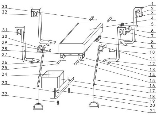
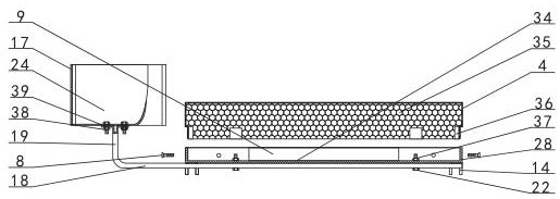
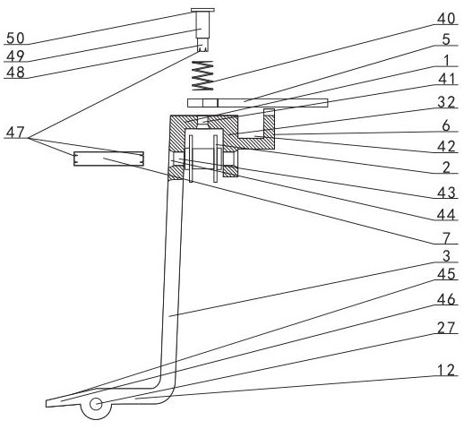
[0027] combined with Figure 1-8 The high-voltage cable operation trolley described in includes a cushion 4, a hanging arm, a sheave 2, a lever 16, a foot cover 21, a U-shaped plate 11 and a tool box 17. The lower ends of the vertical rods 3 are hingedly connected, and a sheave 2 is arranged on the outside of the upper end of each hanging arm vertical rod 3, and the middle parts of the vertical rods 3 on both sides of the front part of the seat cushion 4 are respectively provided with shaft holes A10, and the middle parts of the two levers 16 are respectively provided...


PUM


Abstract

A high-voltage cable operation trolley, relating to a high-voltage cable maintenance trolley, the lower parts of the front and rear sides of the seat cushion (4) are respectively hingedly connected with the lower ends of four hanging arms (3), and the vertical poles (3) of each hanging arm The outside of the upper end of the seat is provided with a sheave (2), the middle part of the upright bar (3) on both sides of the front part of the seat cushion (4) is hingedly connected with the middle part of the lever (16) respectively, and the rear upper outside of the two levers (16) is respectively provided with a U Shaped plate (11), is provided with rubber brake pad (30) on the concave surface of U-shaped plate (11), and the front lower part of two levers (16) is respectively provided with foot cover (21), and the front part of cushion (4) A toolbox (17) is provided; the present invention utilizes the four hanging arms provided on the cushion to hang on the high-voltage cable respectively, and the U-shaped plate forms a brake on the high-voltage cable by the control lever of the two-legged cover, thereby obtaining stable pressure on the high-voltage cable. Job maintenance.

Description

【Technical field】 [0001] The invention relates to a high-voltage cable maintenance trolley, in particular the invention relates to a high-voltage cable operation trolley. 【Background technique】 [0002] It is well known that high-voltage or ultra-high-voltage lines are the main way of long-distance electric energy transmission, and high-voltage cables are bridges between power supply equipment and electric equipment, and play the role of transmitting electric energy; they are widely used, so failures often occur, and the high-voltage cables used The cables are bare wires. During long-term use, the spacers on the high-voltage cables are "roughly divided into one-shaped, Y-shaped, X-shaped, wooden-shaped or rice-shaped according to the number of lines", and parts are prone to missing parts due to long-term wind force, so Regular maintenance is required; high-voltage cables in heavy ice areas are affected by de-icing operations, which will also cause strand breakage problems; a...

Claims


Application Information

Patent Timeline
Patent Type & Authority Patents(China)
IPC IPC(8): H02G1/02
CPCH02G1/02
Inventor 於伟勇
Owner 山东辰之翼信息科技有限公司
Why Eureka
Try Eureka