
Negative-pressure-driven self-powered lighting dust collector floor brush and working method thereof

A vacuum cleaner, self-powered technology, applied in the installation of vacuum cleaners, electrical equipment, cleaning equipment, etc., can solve the problems of large occupied area, unsuitable for small and micro vacuum cleaners, high failure risk, and achieve the effect of reducing the total occupied space

Pending Publication Date: 2021-01-29
SUZHOU EULOGY ELECTRICAL APPLIANCE
View PDF0 Cites 1 Cited by
  • Summary
  • Abstract
  • Description
  • Claims
  • Application Information

AI Technical Summary

Problems solved by technology

[0002] The vacuum cleaner can remove dust and garbage, mainly because its motor rotates at high speed, and the suction port sucks dusty air. The motor will generate strong suction and pressure at a speed of 500 cycles per second. The air in the dust-absorbing part of the front end of the motor continuously replenishes the air in the fan, resulting in an instantaneous vacuum inside the vacuum cleaner and a negative pressure difference with the outside atmospheric pressure. Under the action of this pressure difference, dust and other debris pass through the carpet or floor in turn. Brushes, long pipes, elbows, hoses, and hose joints enter the dust filter bag, and dust and other debris remain in the dust filter bag. After the air is purified by the filter, it is discharged from the rear of the body. However, sometimes there is a problem. When the light source is relatively dark or in dark conditions, the vacuum cleaner cannot clean the floor cleanly
[0003] For the convenience of operation, the switch of the lighting device is generally installed directly on the handle of the vacuum cleaner, and the wiring between the switch and the lighting device passes through the air duct of the vacuum cleaner, but the materials and assembly costs of the wires and multiple connection parts are high, and joints that need to be connected More lead to a higher risk of failure in later use
[0004] In order to solve this problem, a newer technical solution is to directly install the lighting device and the battery box for power supply together with the lighting device inside the floor brush of the vacuum cleaner. The problem with this technical solution is that the power supply of the lighting device is an independent dry battery, and the battery When it is exhausted, the floor brush needs to be disassembled to replace the battery, and the battery, switch and lamp beads need to be arranged in a circuit, which occupies a large area and is not suitable for small and micro vacuum cleaners

Method used


Image

  • Negative-pressure-driven self-powered lighting dust collector floor brush and working method thereof
  • Negative-pressure-driven self-powered lighting dust collector floor brush and working method thereof

Examples


Embodiment 1

[0027] Embodiment 1: A working method for negative pressure-driven self-powered lighting vacuum cleaner floor brush, comprising the following steps:

[0028] (1) Start the vacuum cleaner, and a negative pressure is formed inside the vacuum cleaner;

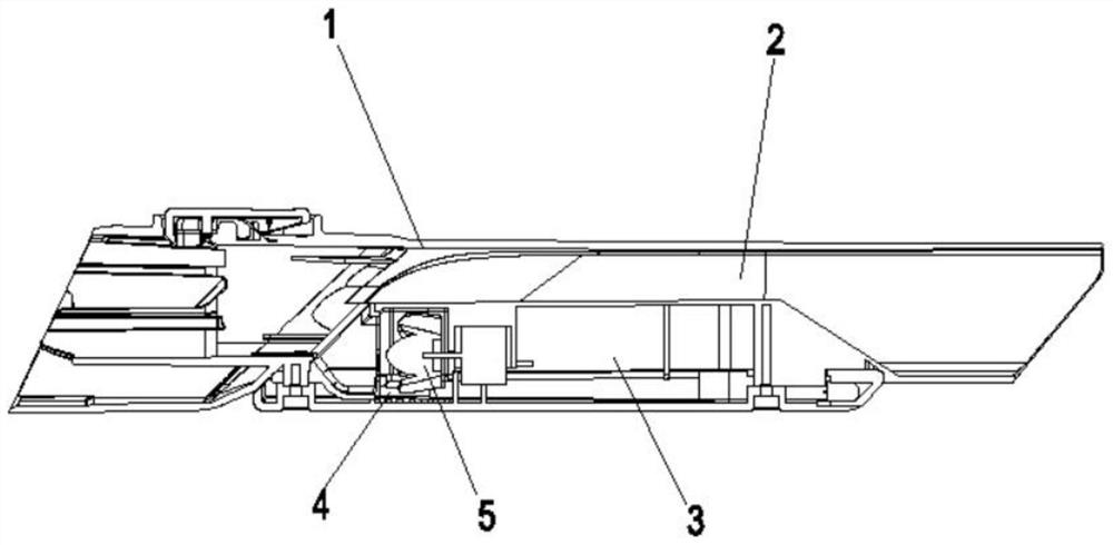
[0029] (2) The negative pressure inside the vacuum cleaner and the external atmospheric pressure form a pressure difference, thereby causing the airflow to flow, and when the negative pressure reaches -0.3kpa, the negative pressure wind blade power generation wheel set 5 starts to rotate to generate electricity;

[0030] (3) The obtained electric energy is sent to the LED lamp beads, and the LED lamp beads emit light to meet the lighting requirements.


PUM


Abstract

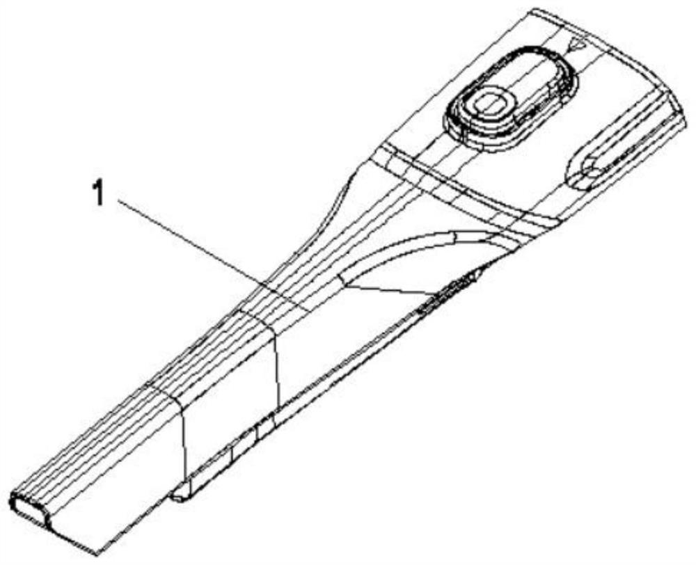
The invention discloses a negative-pressure-driven self-energized lighting dust collector floor brush and a working method thereof. The negative-pressure-driven self-energized lighting dust collectorfloor brush comprises a floor brush body and a lighting device arranged in the floor brush body, wherein the lighting device comprises LED lamp beads and a negative-pressure fan blade power generationwheel set connected to the LED lamp beads; the floor brush body comprises a main air duct, an impeller air duct and an impeller bin communicated with the tail end of the impeller air duct, the negative-pressure fan blade power generation wheel set is installed in the impeller bin, the tail end of the impeller air duct directly faces blades on one side of the negative-pressure fan blade power generation wheel set, and the impeller air duct is tightly attached to and arranged on the main air duct in a parallel off-axis mode; The negative-pressure-driven self-energized lighting dust collector floor brush is advantaged in that a wire and a battery are not needed, the LED lamp beads are turned on and turned off along with starting of the dust collector, automatic lighting is achieved, the LEDlamp beads do not need to be turned on and turned off manually, use and operation are convenient, and material cost is reduced.

Description

technical field [0001] The invention relates to the field of vacuum cleaners, in particular to a negative pressure driven self-powered lighting vacuum cleaner brush and its working method. Background technique [0002] The vacuum cleaner can remove dust and garbage, mainly because its motor rotates at high speed, and the suction port sucks dusty air. The motor will generate strong suction and pressure at a speed of 500 cycles per second. The air in the dust-absorbing part of the front end of the motor continuously replenishes the air in the fan, resulting in an instantaneous vacuum inside the vacuum cleaner and a negative pressure difference with the outside atmospheric pressure. Under the action of this pressure difference, dust and other debris pass through the carpet or floor in turn. Brushes, long pipes, elbows, hoses, and hose joints enter the dust filter bag, and dust and other debris remain in the dust filter bag. After the air is purified by the filter, it is dischar...

Claims


Application Information

Patent Timeline
IPC IPC(8): A47L5/12A47L9/30A47L9/28A47L9/00
CPCA47L5/12A47L9/30A47L9/2868A47L9/00
Inventor 陆文良
Owner SUZHOU EULOGY ELECTRICAL APPLIANCE
Learn More