A horizontal filter separator for gas transmission field

A filter separator, horizontal technology, applied in the field of horizontal filter separators in gas transmission fields, can solve the problems of shortening the service life of the filter element 14, clogging of the filter chamber 1, and affecting the quality of downstream natural gas, etc.

Active Publication Date: 2022-06-03
PETROCHINA CO LTD
View PDF11 Cites 0 Cited by
  • Summary
  • Abstract
  • Description
  • Claims
  • Application Information

AI Technical Summary

Problems solved by technology

The sewage outlet 31 of the filter chamber of the existing horizontal filter separator is far away from the blind plate 11, and is arranged in the middle of the filter chamber 1 or near the downstream deflector 13, and the dust mostly gathers at the blind plate 11 to the upstream deflector 12, relatively Since the sewage outlet 31 of the filter chamber is located far away, only a small amount of dust in the filter chamber 1 can be discharged from the sewage outlet 31 of the filter chamber during sewage discharge, and the remaining dust will accumulate between the blind plate 11 and the upstream guide plate 12, resulting in horizontal filtration. The pressure difference of the separator increases, thereby shortening the service life of the filter element 14, affecting the gas quality of the downstream natural gas, and even causing the blockage of the filter chamber 1 in severe cases

Method used


Image

  • A horizontal filter separator for gas transmission field
  • A horizontal filter separator for gas transmission field
  • A horizontal filter separator for gas transmission field

Examples


Embodiment Construction

[0038] In order to make the objectives, technical solutions and advantages of the present invention clearer, the present invention will be further described in detail below with reference to the accompanying drawings.

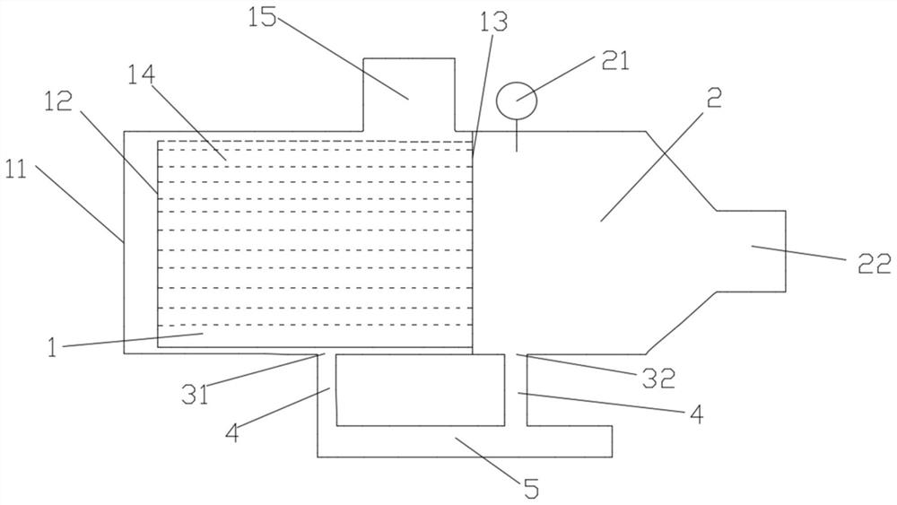
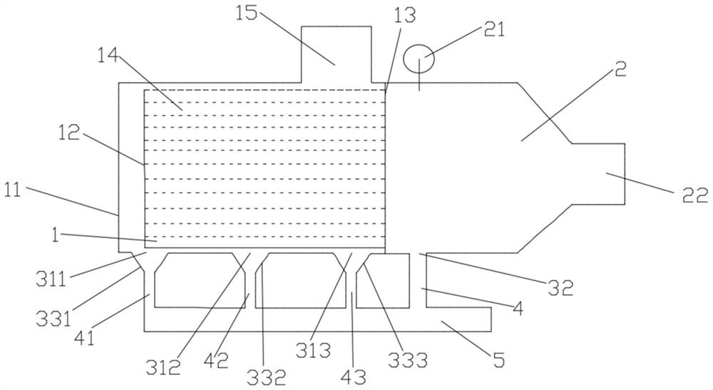
[0039] like figure 2As shown, the horizontal filter separator for gas transmission field disclosed by the present invention includes a cavity, a filter element 14, a blind plate 11, an upstream guide plate 12 and a downstream guide plate 13. One end of the cavity is sealed by the blind plate 11, and the cavity is The other end of the body is provided with a gas outlet 22. In the cavity, an upstream deflector 12 and a downstream deflector 13 are arranged in sequence from the blind plate 11 end to the gas outlet 22 end. Both the upstream deflector 12 and the downstream deflector 13 are vertical. are arranged and parallel to each other, the cavity between the blind plate 11 and the downstream guide plate 13 in the cavity is the filter cavity 1, the filter element...


PUM


Abstract

The invention discloses a horizontal filter separator for a gas transmission field, which includes a cavity, a filter element, a blind plate, an upstream deflector and a downstream deflector. One end of the cavity is sealed by a blind plate, and the other end is opened with a gas outlet. The upstream deflector and the downstream deflector are arranged in sequence from the end of the blind plate to the gas outlet in the body. The chamber between the blind plate and the downstream deflector is a filter cavity, and the filter element is set in the filter cavity. Inlet, the bottom of the filter cavity is provided with the sewage outlet of the first filter cavity, the sewage discharge port of the second filter cavity and the sewage discharge port of the third filter cavity. In the middle of the bottom surface of the cavity, the sewage outlet of the third filter cavity is located near the downstream deflector of the filter cavity. The horizontal filter separator for the gas transmission field provided by the present invention can discharge the dust from the blind plate to the upstream guide plate, can reduce the influence of dust accumulation on the filter element, and improve the filter efficiency and service life of the filter element.

Description

technical field [0001] The invention relates to the field of oil and gas storage and transportation filtration, in particular to a horizontal filter separator for gas transmission fields. Background technique [0002] After the natural gas is extracted, it contains a large amount of impurities such as dust. The impurities such as dust enter the lower process, which affects the normal production and safety. After the natural gas is extracted, it needs to be filtered and separated before it can be transported downstream. [0003] like figure 1 As shown, the horizontal filter separator currently used in the gas transmission field includes a cavity, a filter element 14, a blind plate 11, an upstream deflector 12 and a downstream deflector 13. One end of the cavity is sealed by a blind plate 11, and the blind plate 11 It is detachably connected to the cavity. The other end of the cavity is provided with a gas outlet 22. The cavity is provided with an upstream guide plate 12 and ...

Claims


Application Information

Patent Timeline
Patent Type & Authority Patents(China)
IPC IPC(8): B01D46/88B01D46/48C10L3/10
CPCB01D46/00B01D46/48C10L3/101B01D46/88
Inventor 赵明郑思佳刘颖罗敏别沁田园媛陈莉彭基华
Owner PETROCHINA CO LTD
Why Eureka
Try Eureka