

Developing method and apparatus using two-ingredient developer with prescribed coating of particles and resin
a technology of developer and developer, which is applied in the field of developing methods using two-ingredient developer and image forming apparatus, can solve the problems of inability to stably charge developer, deterioration of carrier grains, and varying ratios of toner and carrier mixture, and achieve the effect of high image quality
- Summary
- Abstract
- Description
- Claims
- Application Information
AI Technical Summary
Benefits of technology
Problems solved by technology
Method used
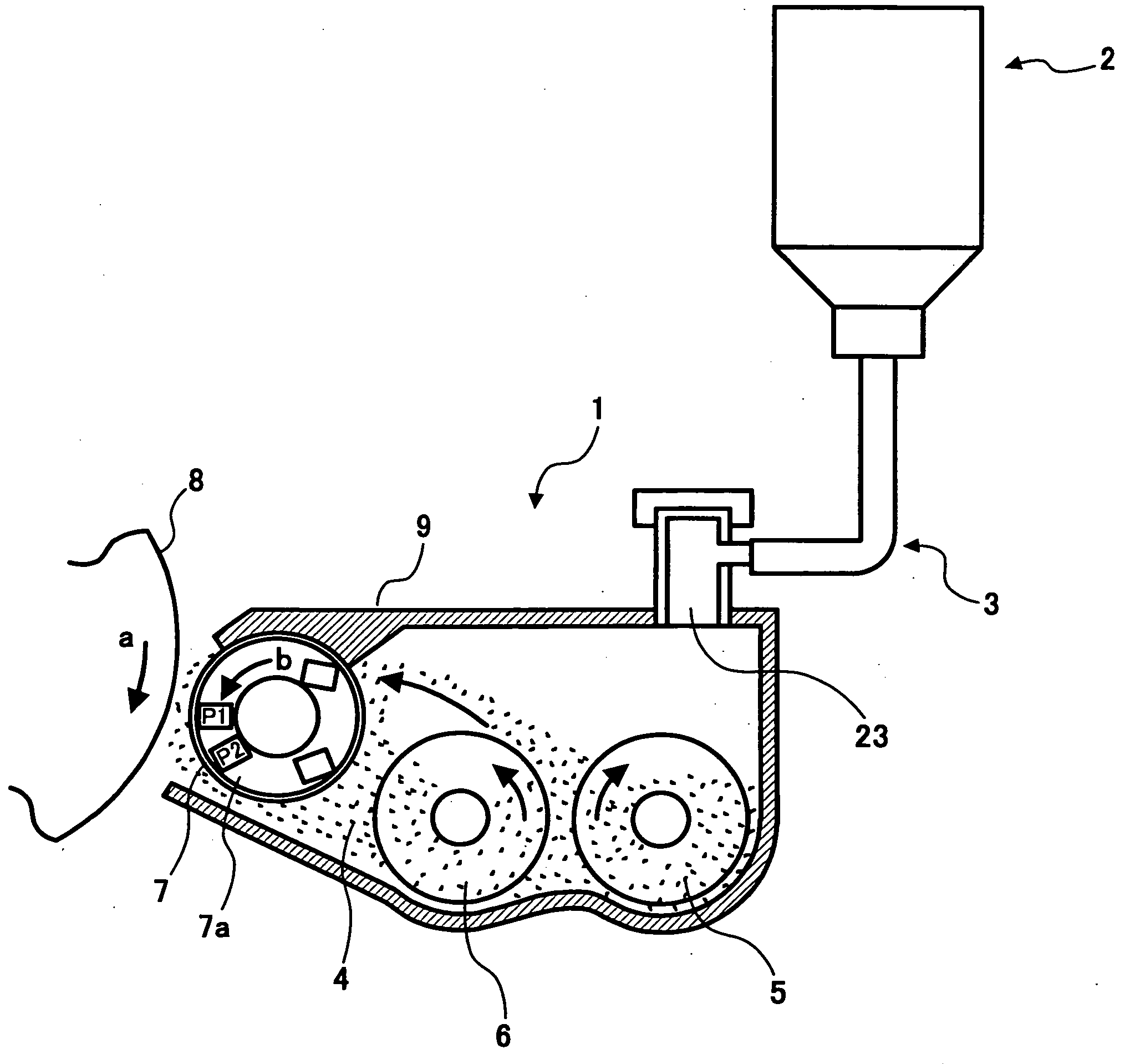
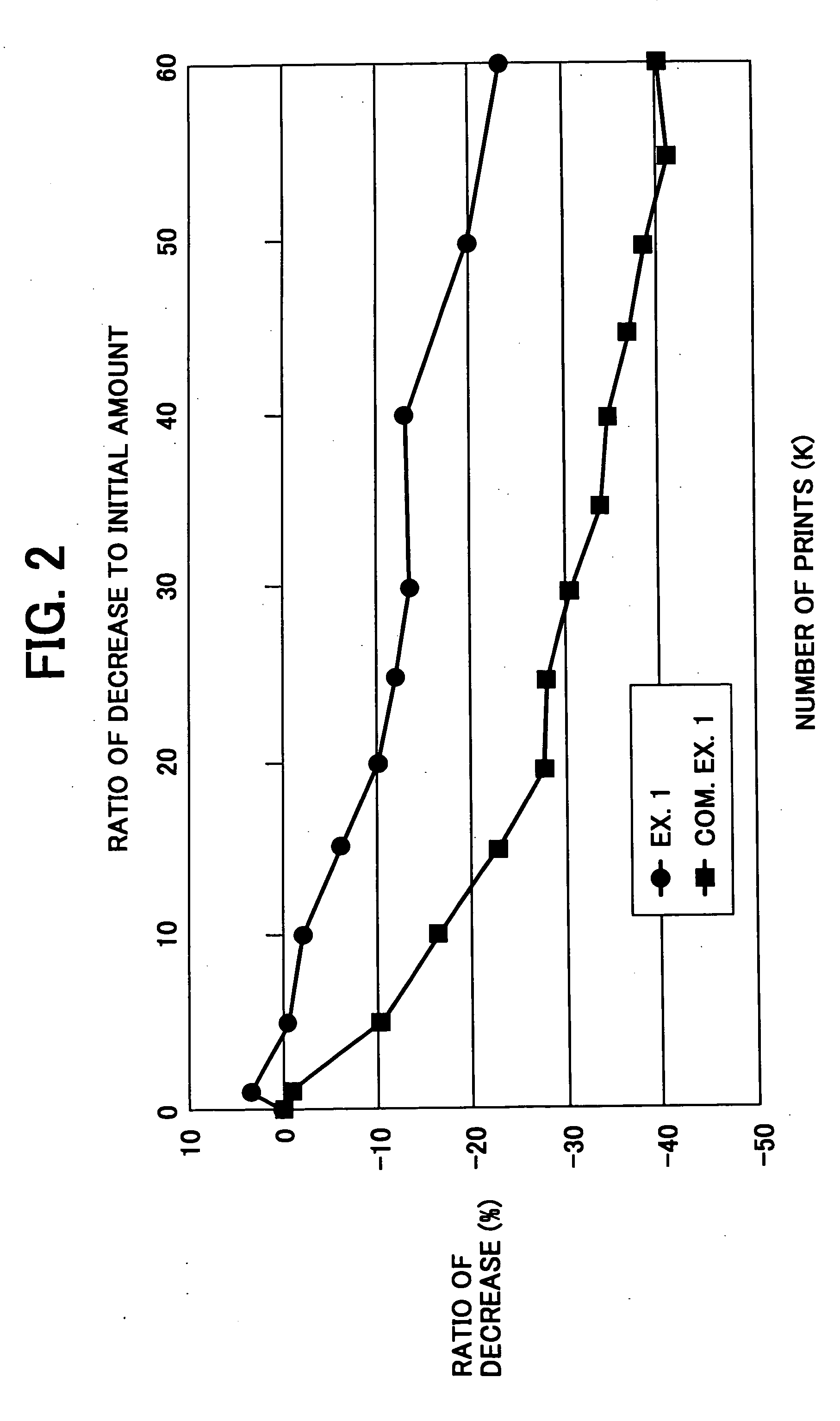
Image

Examples
example 1
[0113] 56.0 parts of acrylic resin solution (50 wt % of solid), 15.6 parts of guanamine solution, 160.0 parts of alumina grains (0.3 μm; resistivity of 1014 Ω·cm), 900 parts of toluene and 900 parts of butyl cellosolve were dispersed in a homomixer for 10 minutes to thereby prepare a film forming solution. The film forming solution was coated on cores, which were implemented by sintered ferrite F-300, by Spilacoater to thickness of 0.15 μm and then dried. The resulting carrier grains were left in an electric furnace at 150° C. for 1 hour. The carrier grains had a weight-mean grain size of 35 μm. The ratio of the grain size D (0.3 m) of the alumina grains contained in the coating layer to the thickness h (0.15 μm) of the binder resin layer, i.e., D / h is 2.0.
[0114] Again, the above thickness of the binder resin layer is represented by the mean thickness of the layers of the carrier grains.
example
[0139] 56.0 parts of acrylic resin solution (50 wt % of solid), 15.6 parts of guanamine solution, 160.0 parts of alumina grains (0.3 μm; resistivity of 1014 Ω·cm), 900 parts of toluene and 900 parts of butyl cellosolve were dispersed in a homomixer for 10 minutes to thereby prepare a film forming solution. The film forming solution was coated on cores, which were implemented by sintered ferrite F-300 by Spilacoater to thickness of 0.15 μm and then dried. The resulting carrier grains were left in an electric furnace at 150° C. for 1 hour and then cooled off. The resulting ferrite powder bulk was classified by a 100 μm sieve to thereby produce carrier grains. The ratio of the grain size D (0.3 m) of the alumina grains contained in the coating layers to the thickness h (0.15 μm) of the binder resin layer, i.e., D / h is 2.0.
[0140] Again, the thickness of the binder resin layer is represented by the mean thickness of the layers of the carrier grains.
PUM
 Abstract
Description
Claims
Application Information