Plastic film processing dust removal system
A technology of dust removal system and plastic film, which is applied in the direction of removing smoke and dust, processing thin materials, and cleaning methods by using tools, etc., can solve the problems of low dust removal efficiency, influence of later use, inconvenient use, etc., so as to improve the rolling efficiency and avoid folding. , the effect of avoiding secondary pollution
- Summary
- Abstract
- Description
- Claims
- Application Information
AI Technical Summary
Problems solved by technology
Method used
Image

Examples
specific Embodiment approach 1
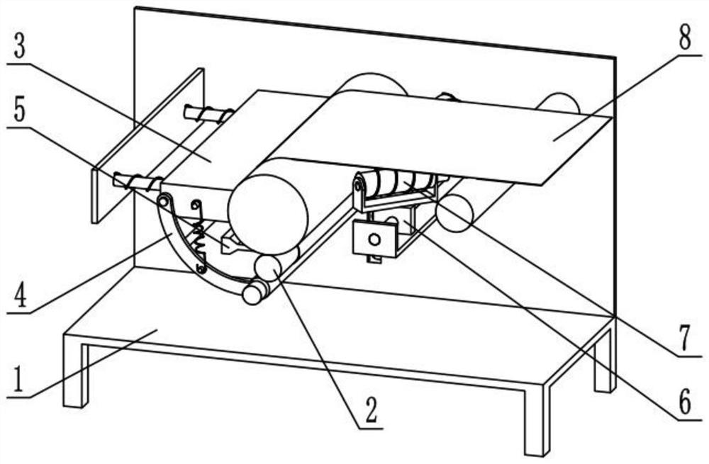
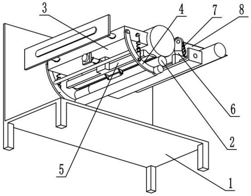
[0029]Such asFigure 1-10As shown, a plastic film processing and dust removal system includes a supporting main frame 1, a winding mechanism 2, a dust removal mechanism I3, a dust removal mechanism II4, a dust suction mechanism 5, a width adjustment mechanism 6, an unfolding mechanism 7 and a film 8. The rear end of the mechanism 2 is slidably connected to the support main frame 1, the left end of the dust removal mechanism I3 is slidably connected to the left end of the support main frame 1, and the dust removal mechanism II4 is rotatably connected to the dust removal mechanism I3 and tightens the winding mechanism 2. The dust collection mechanism 5 is slidably connected to the lower end of the dust removal mechanism I3, the dust collection mechanism 5 is located between the dust removal mechanism I3 and the dust removal mechanism II4, and the width adjustment mechanism 6 is connected to the main support frame 1. The unfolding mechanism 7 is provided with two, the two unfolding mech...
specific Embodiment approach 2
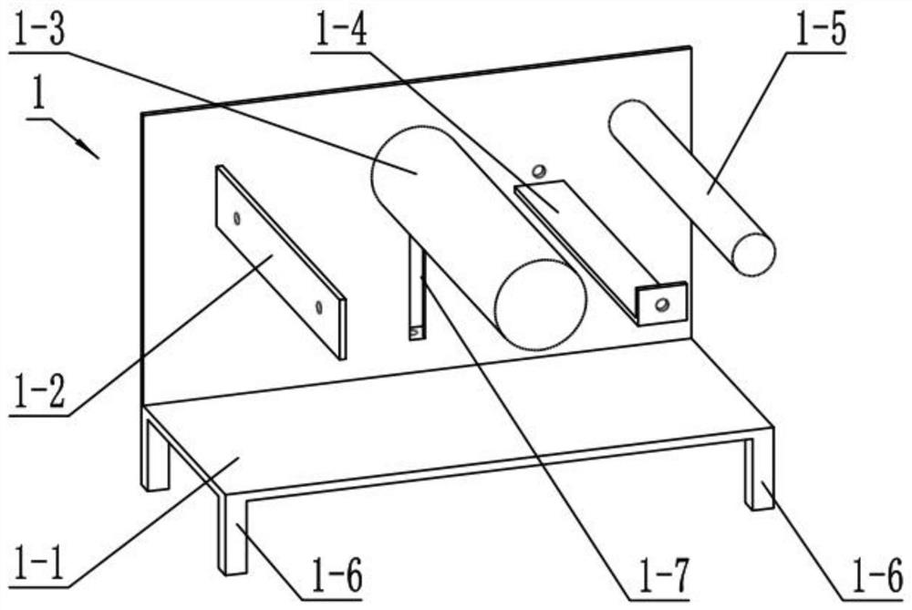
[0032]Such asFigure 1-10As shown, the supporting main frame 1 includes a main frame plate 1-1, a mounting plate 1-2, a supporting roller 1-3, a mounting seat plate 1-4, a guide roller 1-5, a supporting leg 1-6, and a sliding plate. Holes 1-7 and fixing plates 1-8, the four corners of the lower end of the main frame plate 1-1 are fixedly connected with support legs 1-6, and the rear ends of the mounting plate 1-2 and the mounting seat plate 1-4 are fixedly connected to On the main frame plate 1-1, the back ends of the support rollers 1-3 and the guide rollers 1-5 are all rotatably connected to the main frame plate 1-1, and the mounting plate 1-2 is located at the left end of the main frame plate 1-1. The seat plate 1-4 is located between the support roller 1-3 and the guide roller 1-5, the sliding hole 1-7 is arranged on the main frame plate 1-1, and the fixed plate 1-8 is fixedly connected to the lower end of the sliding hole 1-7 .
[0033]The guide roller 1-5 is used to guide the film...
specific Embodiment approach 3
[0035]Such asFigure 1-10As shown, the winding mechanism 2 includes a lifting seat 2-1, a lifting sliding column 2-2, a spring 2-3, a winding motor 2-4, and a winding installation shaft 2-5. The lifting seat 2-1 is slidably connected to the sliding In holes 1-7, the rear end of the winding mounting shaft 2-5 is rotatably connected to the lifting base 2-1, the winding motor 2-4 is fixedly connected to the lifting base 2-1, and the output shaft is fixed to the winding mounting shaft 2-5 Connection, the upper end of the lifting sliding column 2-2 is fixedly connected to the lifting seat 2-1, the lifting sliding column 2-2 is slidingly connected in the fixed plate 1-8, and the spring 2-3 is sleeved on the lifting sliding column 2-2 , The two ends of the spring 2-3 are respectively the top lifting seat 2-1 and the fixed plate 1-8, the winding mounting shaft 2-5 presses the supporting roller 1-3, the film 8 is passed by the guide roller 1-5 at the right end of the device through the suppor...
PUM
 Abstract
Description
Claims
Application Information
 - R&D
- Intellectual Property
- Life Sciences
- Materials
- Tech Scout
- Unparalleled Data Quality
- Higher Quality Content
- 60% Fewer Hallucinations
Browse by: Latest US Patents, China's latest patents, Technical Efficacy Thesaurus, Application Domain, Technology Topic, Popular Technical Reports.
© 2025 PatSnap. All rights reserved.Legal|Privacy policy|Modern Slavery Act Transparency Statement|Sitemap|About US| Contact US: help@patsnap.com