Die cutter splicing device and method of full-automatic bending equipment

A fully automatic, bending die technology, applied in the field of sheet metal bending, can solve the problems of affecting processing accuracy, unable to meet the needs of small batch and multi-variety processing, and low degree of intelligence, and achieve the effect of improving processing accuracy.

Active Publication Date: 2021-01-29
南京云上自动化科技有限公司
View PDF11 Cites 3 Cited by
  • Summary
  • Abstract
  • Description
  • Claims
  • Application Information

AI Technical Summary

Problems solved by technology

[0010] When there is no mold length adjustment, every time the processing part is switched, it needs to be shut down for manual operation, which obviously cannot meet the processing needs of small batches and multiple varieties, and the degree of intelligence is too low
In addition, when adjusting the molds, if the gaps between the N-segment molds are different in size, they cannot be evenly divided. In this way, where the gaps between the molds are large, the machining accuracy will be seriously affected

Method used


Image

  • Die cutter splicing device and method of full-automatic bending equipment
  • Die cutter splicing device and method of full-automatic bending equipment
  • Die cutter splicing device and method of full-automatic bending equipment

Examples


Embodiment 1

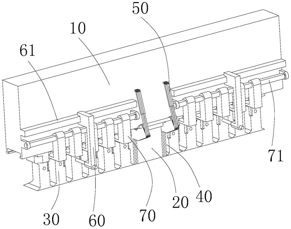
[0116] Such as Figure 17 As shown, the mold distance equidistant mechanism includes a rotating shaft 71, several wedge blocks 73 and equally divided moving arms 72 equal in number to the wedge blocks. A wedge-shaped block is respectively arranged between two adjacent moving molds and between the moving mold and the adjacent adjusting mold.

[0117] Each wedge-shaped block is perpendicular to the length direction of the mold seat, and the inner end of each wedge-shaped block has two guiding slopes 731 arranged symmetrically. The two guide slopes can slide and cooperate with the fixed guide surface and the movable guide surface respectively.

[0118] The rotating shaft is installed on the side wall of the mold seat and is parallel to the length direction of the mold seat, and the rotating shaft can rotate around its own axis under the action of the rotating shaft driving device.

[0119] There can be one or two rotating shafts. In this embodiment, there are preferably two rot...

Embodiment 2

[0126] Such as Figure 20 with Figure 21 As shown, the mold distance equalization mechanism includes several springs, one spring is respectively arranged between two adjacent moving molds and between the moving mold and the adjacent adjusting mold, and each spring is arranged along the length direction of the mold seat.

[0127] The preferred installation method of the spring located between two adjacent movable molds is as follows: the opposite sides of the two adjacent movable molds are preferably provided with spring installation grooves, and the two ends of the spring are respectively located in the spring installation grooves. One end or both ends of the spring are respectively connected with the spring installation groove.

[0128] The installation method of the spring located between the movable mold and the adjacent adjusting mold is as follows: a spring installation groove is arranged in the movable mold facing the adjusting mold, one end of the spring is connected ...

specific example

[0132] Specific example: the width of the fixed mold is 80mm, the width of each movable mold is 100mm, and the width of each adjusting mold is 10mm. When the total length L of the required bending die is 703mm, the selected combination method is: L=80 (fixed die) + 6*100 (movable die) + 2*10 (adjusting die) + 3mm (gap). That is to say, it is necessary to select 6 moving dies and 2 adjusting dies, further, 3 left moving dies, 3 right moving dies, 1 left adjusting die and 1 right adjusting die.

[0133] The mold distance equalizing mechanism in the present invention will make the above-mentioned 3mm gap evenly distributed between each moving mold.

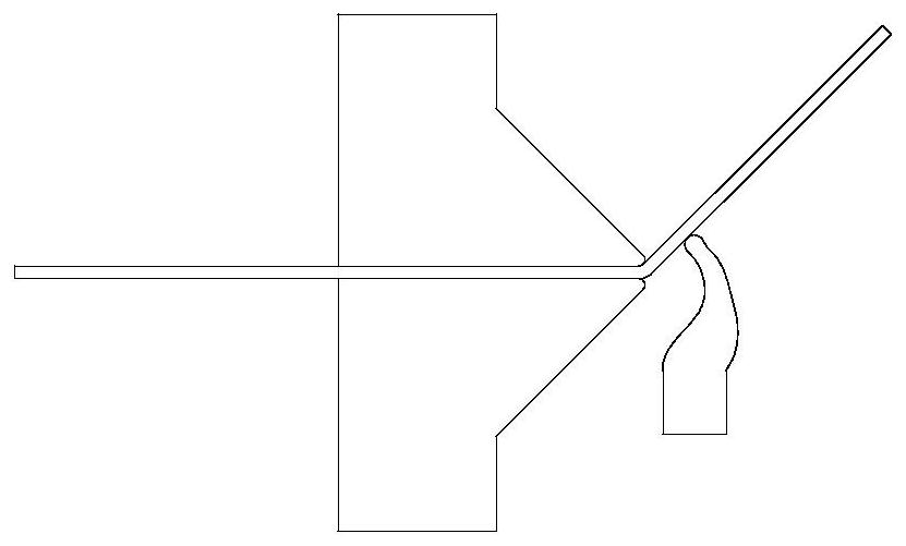
[0134] Step 2, Adjusting mold flipping: According to the number of adjusting molds m selected in step 1, all the remaining unselected adjusting molds far away from the fixed mold are turned upward and lifted away from the mold assembly position through the adjusting mold turning mechanism.

[0135] Step 3, Unlocking the mobile mold:...


PUM


Abstract

The invention discloses a die cutter splicing device and method of full-automatic bending equipment. The die cutter splicing device comprises a die base, a bending die, an adjusting die overturning mechanism, a die moving mechanism and a die distance equally-dividing mechanism. The bending die comprises a fixed die, movable dies and adjusting dies; the fixed die is mounted in the bottom center ofthe die base; the adjusting dies are symmetrically arranged on the two sides of the fixed die; each adjusting die can be over turned outwards; the movable dies are symmetrically arranged on the two sides of the adjusting dies and can slide and be locked; each movable die is provided with a fixed guide surface and a movable guide surface; the die distance equally-dividing mechanism comprises a plurality of wedge-shaped blocks; each wedge-shaped block is provided with two guide inclined planes which are symmetrically distributed and can be in sliding fit with the corresponding fixed guide surface and the corresponding movable guide surface respectively; and all the wedge-shaped blocks can swing synchronously. According to the die cutter splicing device and method of the full-automatic bending equipment provided by the invention, the length of the bending die can be automatically adjusted, gaps between the dies can be equally divided while adjustment is conducted, and the machining precision is greatly improved, so that the flexible machining requirements of non-standard workpieces in multiple varieties, small batches and the like are met.

Description

technical field [0001] The invention relates to the field of sheet metal bending, in particular to a mold knife-joining device and method for automatic bending equipment. Background technique [0002] In the field of industrial production, the proportion of metal sheets is very high. Taking the automobile industry as an example, the proportion of metal sheet forming and processing accounts for about 60%. In the white goods industry, the proportion of metal sheet processing accounts for about 50%. Electrical cabinets, express cabinets, cabinets , File cabinets and other industries sheet metal processing accounted for more than 95%. [0003] In recent years, CNC sheet metal processing equipment is developing in the direction of automation, intelligence, high speed and high precision. In the sheet metal forming industry, sheet bending is the most difficult process, and it is also the most difficult process to realize automation. Its overall technical level determines the tech...

Claims


Application Information

Patent Timeline
Patent Type & Authority Applications(China)
IPC IPC(8): B21D5/02B21D37/12B21D37/02
CPCB21D5/0227B21D5/0209
Inventor 徐丰羽华德荣陈自新
Owner 南京云上自动化科技有限公司
Why Eureka
Try Eureka