Yarn textile printing and dyeing product scutching equipment

A technology for textile printing and dyeing and yarn quality, which is applied to the field of textile printing, dyeing and dehydration, can solve the problems of unsatisfactory, failed opening, low yarn quality textile opening effect, etc., and achieve the effect of effective connection

Inactive Publication Date: 2017-06-20
潘杰
View PDF1 Cites 1 Cited by
  • Summary
  • Abstract
  • Description
  • Claims
  • Application Information

AI Technical Summary

Problems solved by technology

[0002] In modern printing and dyeing textile enterprises, the textile printing and dyeing process is processed in a rope shape. After the rope-shaped textiles are separated from the printing and dyeing wastewater, before entering the next process, the rope-shaped textiles need to be untwisted and opened. In the open-width shape; and the existing opening-width equipment is through the cooperation of multiple cloth rollers, and the threads in the opposite direction of rotation are set on the cloth rollers, and the textiles are opened by relying on the cooperation between the thread and the thread between the cloth rollers, but the above-mentioned relying on The method of opening the textiles with cloth rollers is very unsatisfactory for textiles with low thickness, density, and roughness, such as gauze textiles, so there is an urgent need for an opening equipment that can be applied to gauze textiles
[0003] In the Chinese patent with the patent number CN104528450B, an open-width centering machine is disclosed. This device can make the fabric unfolded after untwisting be piled up in the fabric splicing car in an orderly folded state with the selvedges flush or by the fabric roll. Coiling, there will be no gyro effect during coiling, but it still cannot solve the problem of relative sliding of the yarn textiles on the cloth roller due to the factors of thickness, density and roughness during the opening process of the yarn textiles, resulting in opening FAIL TECHNICAL PROBLEMS

Method used


Image

  • Yarn textile printing and dyeing product scutching equipment
  • Yarn textile printing and dyeing product scutching equipment
  • Yarn textile printing and dyeing product scutching equipment

Examples


Embodiment

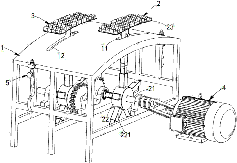
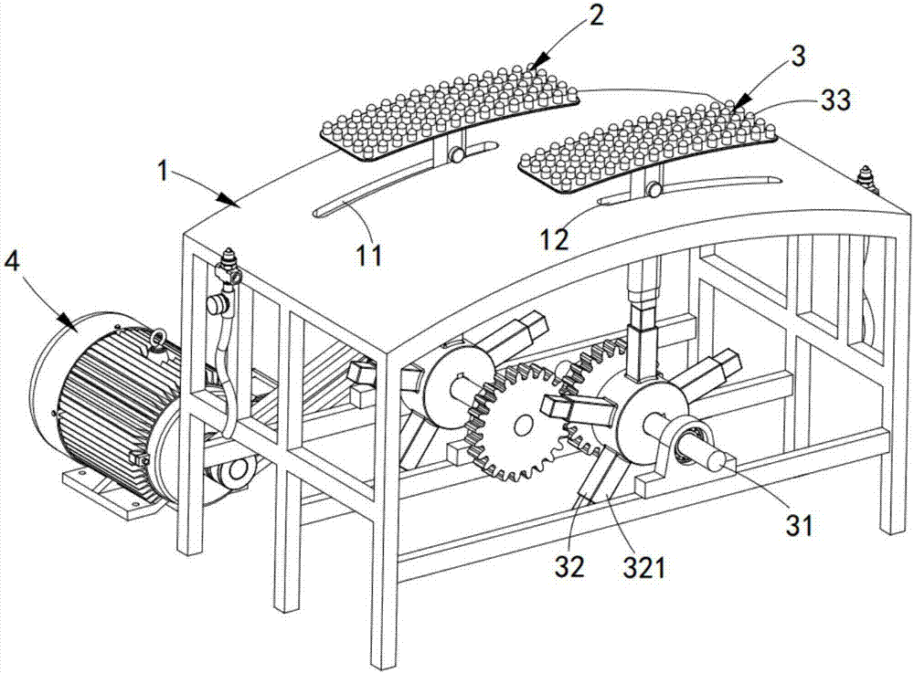
[0051] like figure 1 As shown, a yarn-quality textile printing and dyeing product opening equipment includes a frame 1, a first magnetic opening mechanism 2, a second magnetic opening mechanism 3, a power mechanism 4, and an air injection mechanism 5. The frame 1 The upper surface of the upper surface is provided with a first opening groove 11 and a second opening groove 12, the first opening groove 11 is located at the front side of the second opening groove 12, and the first opening groove 11 and the second opening groove The slots 12 are respectively located on both sides of the frame 1;

[0052] The first magnetic opening mechanism 2 is arranged in the first opening groove 11, and its lower end is connected with the power mechanism 4 through a belt drive;

[0053] The second magnetic opening mechanism 3 is arranged in the second opening groove 12, and its lower end is connected to the first magnetic opening mechanism 2 through gear transmission;

[0054] The power mechan...


PUM


Abstract

The invention discloses a yarn textile printing and dyeing opening equipment, which comprises a frame, a first magnetic opening mechanism, a second magnetic opening mechanism and a power mechanism. The width mechanism and the second magnetic opening mechanism rely on the power mechanism to drive the opening arms in the first magnetic opening mechanism and the second magnetic opening mechanism to reverse synchronously, and wrap the yarn textiles to the two sides of the frame. The side swinging and unfolding realizes the perfect opening of the yarn textiles, and solves the technical problem of the failure of the traditional opening setting due to the thickness, density and roughness of the sandy textiles.

Description

technical field [0001] The invention relates to the technical field of opening-width textile printing and dyeing after dehydration, in particular to an opening-width equipment for yarn-quality textile printing and dyeing products. Background technique [0002] In modern printing and dyeing textile enterprises, the textile printing and dyeing process is processed in a rope shape. After the rope-shaped textiles are separated from the printing and dyeing wastewater, before entering the next process, the rope-shaped textiles need to be untwisted and opened. In the open-width shape; while the existing opening-width equipment cooperates with multiple cloth rollers, and sets threads in the opposite direction of rotation on the cloth rollers, relying on the cooperation between the threads and threads between the cloth rollers to open the textiles, but the above-mentioned relying on The method of opening the textiles with cloth rollers is very unsatisfactory for textiles with low thi...

Claims


Application Information

Patent Timeline
IPC IPC(8): D06C3/00
CPCD06C3/00
Inventor 潘杰
Owner 潘杰
Why Eureka
Try Eureka