Supercharge Your Innovation With Domain-Expert AI Agents!

New energy automobile charging pile mounting mechanism

A new energy vehicle and installation mechanism technology, applied in the direction of electric vehicle charging technology, charging stations, electric vehicles, etc., can solve the problems of laborious installation and disassembly of charging piles, inconvenient use and maintenance, and difficulty in moving charging piles, etc., to achieve Easy to remove, easy to move, simple installation process

Inactive Publication Date: 2021-01-29
株洲瑞尔泰机电科技有限公司
View PDF0 Cites 0 Cited by
  • Summary
  • Abstract
  • Description
  • Claims
  • Application Information

AI Technical Summary

Problems solved by technology

[0004] Most of the existing charging piles are placed directly on the ground, so the charging piles are easy to be damaged if they are not fixed firmly, and the charging piles themselves are difficult to move, and it is inconvenient to use and maintain; some charging piles are directly fixed on the ground with cement, Cement fixation makes the installation and removal of charging piles very laborious

Method used


Image

  • New energy automobile charging pile mounting mechanism
  • New energy automobile charging pile mounting mechanism
  • New energy automobile charging pile mounting mechanism

Examples


Embodiment 1

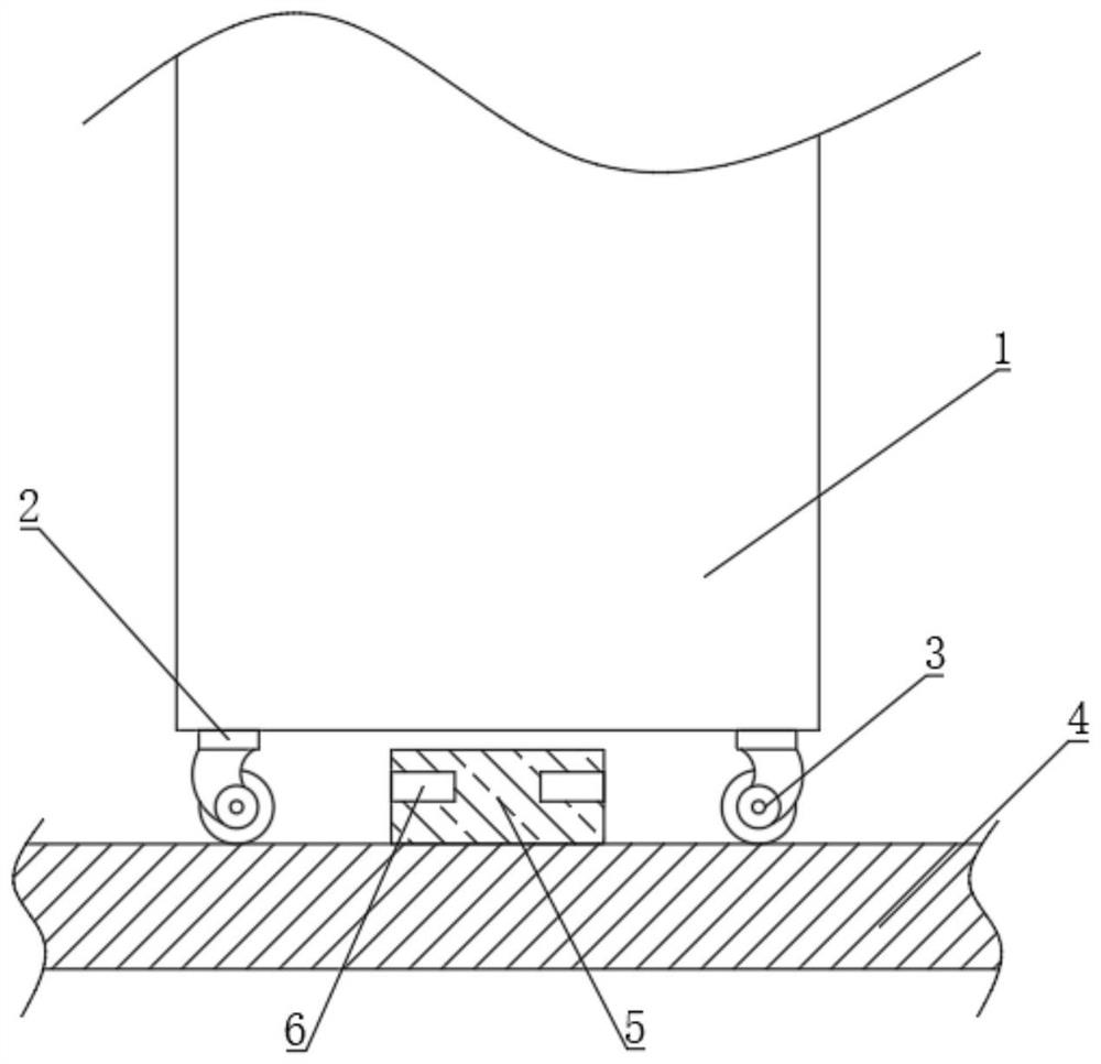
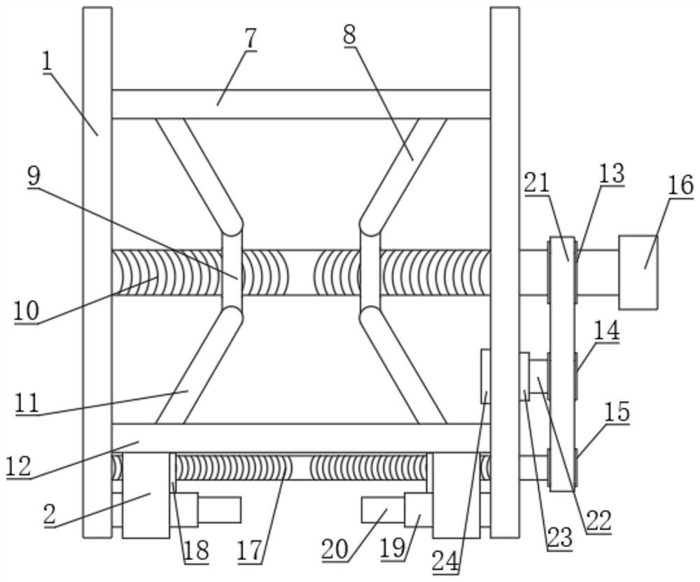
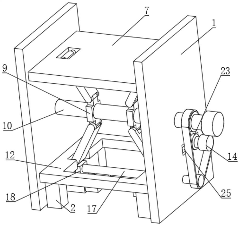
[0030] see Figure 1 to Figure 8 , a new energy vehicle charging pile installation mechanism, including a housing 1 and a rectangular block 5, the interior of the lower end of the housing 1 is provided with a fixed plate 7 and a lifting plate 12, and the left and right ends of the fixed plate 7 are rotated Be connected with upper movable rod 8, the lower end of upper movable rod 8 is rotatably connected with vertical plate 9, the lower end of vertical plate 9 is rotatably connected with lower movable rod 11, and the lower end of lower movable rod 11 is connected with lifting plate 12 in rotation, and lifting plate The bottom surface of 12 is connected with several mounting blocks 2, and the lower end of mounting block 2 is equipped with universal wheel 3, and described vertical plate 9 is provided with threaded hole 1, and threaded hole 1 is connected with threaded shaft 10, and threaded shaft 1 The side of 10 is rotatably connected with housing 1, and threaded shaft 10 is coa...

Embodiment 2

[0036] see Figure 1 to Figure 8 , this embodiment is a further description of the new energy vehicle charging pile installation mechanism described in Example 1. In this embodiment, the telescopic rod 25 is composed of a fixed column 251 and a telescopic column 252, and the fixed column 251 One end is connected to the side of the second through slot 26 , and the other end of the fixing column 251 is provided with a blind hole 254 , which is connected with the telescopic column 252 by sliding fit.

[0037] The bottom surface of the blind hole 254 is connected with a return spring 253, the return spring 253 is connected with one end of the telescopic post 252, and the other end of the telescopic post 252 is fixedly connected with the side of the connecting shaft 22, and the return spring 253 is always in a compressed state. That is, the telescopic rod 25 always applies a thrust to the connecting shaft 22 .

[0038] The first pulley 13, the second pulley 14 and the third pulley...


PUM


Abstract

The new energy automobile charging pile mounting mechanism. The mechanism comprises a shell and a rectangular block, wherein a fixed plate and a lifting plate are arranged in the lower end of the shell, upper movable rods are rotatably connected to the left end and the right end of the fixed plate, vertical plates are rotatably connected to the lower ends of the upper movable rods, and lower movable rods are rotatably connected to the vertical plates; a lower end of the lower movable rod is rotationally connected with a lifting plate, the bottom face of the lifting plate is connected with a plurality of mounting blocks, universal wheels are mounted at the lower ends of the mounting blocks, a first threaded hole is formed in the vertical plate, a first threaded shaft is connected to the first threaded hole in a matched mode, and horizontal plates are fixedly connected to the left side face and the right side face of the shell and located below the lifting plate; blind grooves are formedin the side faces of the horizontal plates, and movable plates are connected into the blind grooves in a sliding fit mode. By arranging the rectangular blocks, the moving plates, the lifting plates and the universal wheels, the novel computer case is convenient to move, the universal wheels can retract into the shell after the novel computer case is installed, meanwhile, the moving plates are inserted into the rectangular blocks, and installation stability is guaranteed.

Description

technical field [0001] The invention relates to the technical field of automobile charging piles, in particular to a new energy automobile charging pile installation mechanism. Background technique [0002] New energy vehicles refer to the use of unconventional vehicle fuels as power sources (or the use of conventional vehicle fuels and new vehicle power devices), and the comprehensive vehicle power control and advanced technology in driving, the formation of advanced technical principles, with New technology, new structure of the car, electric car is a new energy car. [0003] When electric vehicles are charging, they need to use special car charging piles. The function of charging piles is similar to that of fuel dispensers in gas stations. They can be fixed on the ground or walls, and installed in public buildings (public buildings, shopping malls, public parking lots, etc.) and In the parking lot or charging station of the residential area, various types of electric veh...

Claims


Application Information

Patent Timeline
IPC IPC(8): B60L53/31B60B33/04
CPCB60B33/04B60L53/31Y02T10/70Y02T10/7072Y02T90/12
Inventor 杨又伦
Owner 株洲瑞尔泰机电科技有限公司
Features
  • R&D
  • Intellectual Property
  • Life Sciences
  • Materials
  • Tech Scout
  • Unparalleled Data Quality
  • Higher Quality Content
  • 60% Fewer Hallucinations
Learn More