Vertical shaft construction method

A construction method and technology for shafts, which are applied in the directions of cleaning methods using tools, cleaning methods and utensils, chemical instruments and methods, etc., can solve problems such as hole blockage

Inactive Publication Date: 2021-01-29
北京元洋鑫胜建筑工程有限公司
View PDF8 Cites 0 Cited by
  • Summary
  • Abstract
  • Description
  • Claims
  • Application Information

AI Technical Summary

Problems solved by technology

[0004] In view of the above-mentioned related technologies, the inventor believes that there is a defect that when the accumulated water in the shaft enters the sump, there will be impurities such as silt that will block the hole.

Method used


Image

  • Vertical shaft construction method
  • Vertical shaft construction method
  • Vertical shaft construction method

Examples


Embodiment Construction

[0041] The following is attached Figure 1-5 The application is described in further detail.

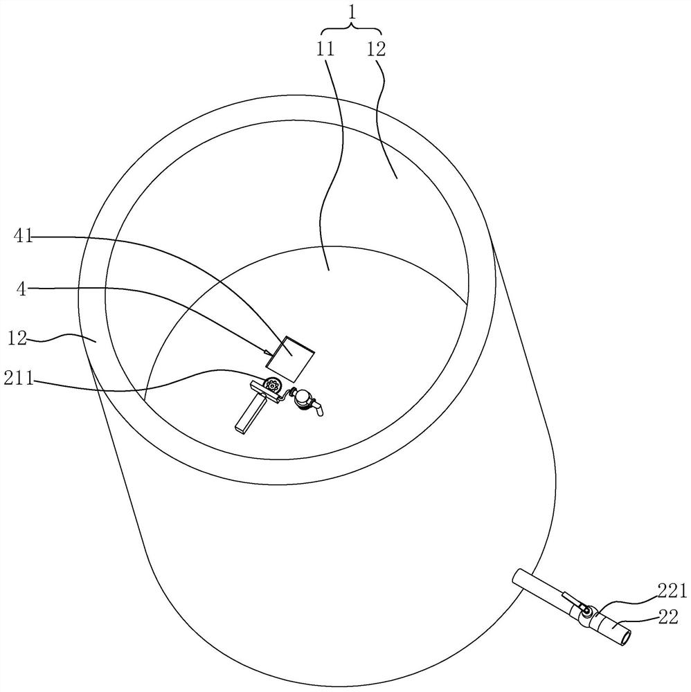
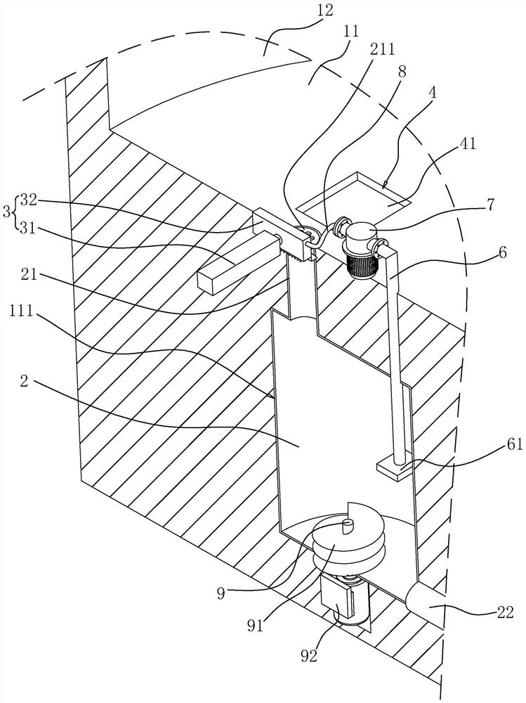
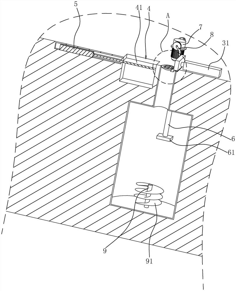
[0042] The embodiment of the application discloses a shaft construction method. refer to figure 1 and figure 2 , the shaft includes a bottom wall 11 and a side wall 12, the bottom wall 11 and the side wall 12 form a shaft space 1, the bottom wall 11 is provided with an installation groove 111, and a water collection tank 2 is arranged in the installation groove 111, and the top of the water collection box 2 is fixedly connected There is a water collection pipe 21, and a filter screen 211 is fixedly installed on the top of the water collection pipe 21. The upper surface of the filter screen 211 is flush with the upper surface of the bottom wall 11, and the bottom wall 11 is inclined to the filter screen 211 side to facilitate the accumulation of water in the shaft. Into the water collecting pipe 21. A drainpipe 22 is fixedly connected to one side of the water collecting tank 2, a...


PUM


Abstract

The invention relates to a vertical shaft construction method, and belongs to the technical field of foundation pit engineering construction. The method includes the steps that (1) a vertical shaft space which comprises a bottom wall and a side wall is excavated; (2) a mounting groove is formed in the bottom wall of the vertical shaft, and a water collecting tank is placed in the mounting groove;(3) a water collecting pipe and a drainage pipe are mounted on the water collecting tank, a filter screen is mounted at a pipe orifice of the water collecting pipe, and a valve is mounted on the drainpipe; (4) a hydraulic cylinder and a push plate are installed beside the drainage pipe on the upper surface of the bottom wall; and (5) a collection pit for containing silt and other impurities is formed in the upper surface of the bottom wall, and a door plate for opening and closing the collection pit is arranged at a pit opening of the collection pit. The vertical shaft construction method hasthe effect of reducing the possibility that the silt and other impurities block the upper surface of the filter screen.

Description

technical field [0001] The present application relates to the technical field of foundation pit engineering construction, in particular to a shaft construction method. Background technique [0002] The bottom of the shaft is the key part of the shaft. During construction and operation, usually due to the seepage of groundwater, the shaft wall often has a certain degree of leakage water, and most of the leakage water on the shaft wall will collect to the bottom of the shaft along the shaft wall. The accumulated water will reduce the structural strength at the bottom of the shaft, and in severe cases, the shaft wall will crack. [0003] The Chinese utility model patent with the authorized announcement number CN207453968U discloses a shaft bottom structure, including a shaft structure and a drainage structure; the shaft structure includes the bottom of the well, and the drainage structure is arranged at the bottom of the well; , the entrance of the central drainage pipe is set...

Claims


Application Information

Patent Timeline
Patent Type & Authority Applications(China)
IPC IPC(8): E02D17/00E02D17/02E02D17/06E03F5/10E03F5/14E03F5/04B08B1/00B08B3/02
CPCB08B1/002B08B3/02B08B3/024E02D17/00E02D17/02E02D17/06E03F5/04E03F5/10E03F5/105E03F5/14
Inventor 王元山王国永孙海明杨立军
Owner 北京元洋鑫胜建筑工程有限公司
Why Eureka
Try Eureka