Working cavity structure of hydraulic retarder

A hydraulic retarder and working chamber technology, applied in the direction of liquid resistance brakes, brake types, brake components, etc., can solve the problems of inconvenient fluid inflow and outflow, large space occupation of the working chamber, and inability to reduce fluid resistance, etc. It achieves the effects of easy normal rotation, simple layout and avoiding difficulty in oil discharge

Pending Publication Date: 2022-07-01
FAWER AUTOMOTIVE PARTS
View PDF8 Cites 0 Cited by
  • Summary
  • Abstract
  • Description
  • Claims
  • Application Information

AI Technical Summary

Problems solved by technology

[0004] However, because the existing working chamber cannot reduce the fluid resistance, the fluid is not easy to flow in and out smoothly, and there will be difficulties in the fluid entering and exiting; moreover, the existing working chamber occupies a large space, cannot be effectively reduced, and has a complex structure

Method used


Image

  • Working cavity structure of hydraulic retarder
  • Working cavity structure of hydraulic retarder
  • Working cavity structure of hydraulic retarder

Examples


Embodiment Construction

[0025] In order to facilitate the understanding of those skilled in the art, the present invention will be further described below with reference to the embodiments and the accompanying drawings, and the contents mentioned in the embodiments are not intended to limit the present invention.

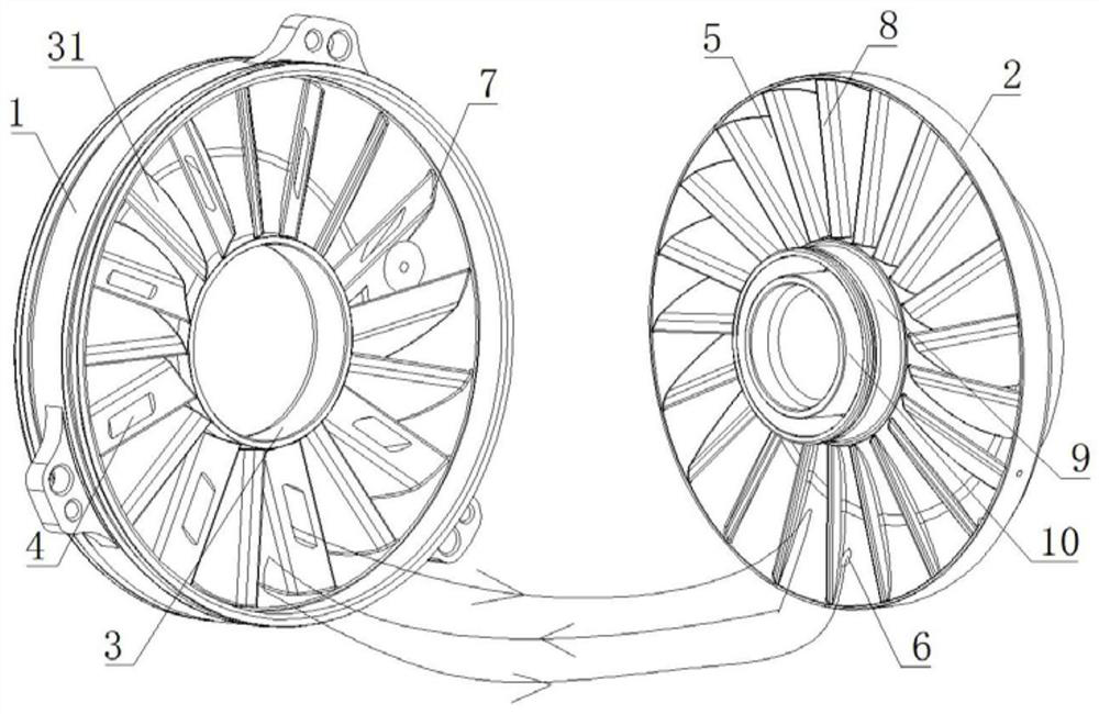
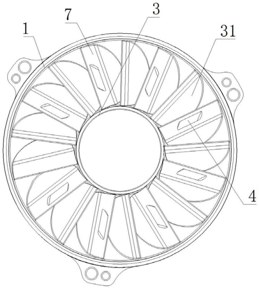
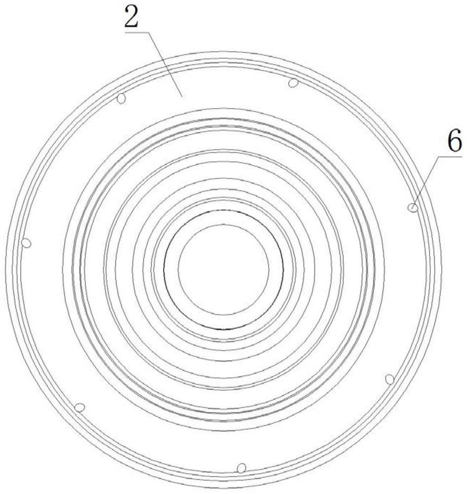
[0026] like Figure 1-3 As shown in the figure, a working cavity structure of a hydraulic retarder includes a first blisk 1 and a second blisk 2 which are both hollow structures, the first blisk 1 and the second blisk 2 are coaxially matched, and the first blisk 1 and the second blisk 2 are coaxially matched. A first impeller 3 is coaxially connected to the disc 1, a first oil port 4 is eccentrically opened on the first impeller 3, a second impeller 5 is coaxially connected to the second leaf disc 2, and the inner wall of the second leaf disc 2 A second oil port 6 is opened in the circumferential direction.

[0027] like Figure 1-3 As shown, in this embodiment, the middle part of the fi...


PUM


Abstract

The invention relates to the technical field of hydraulic retarders, in particular to a working cavity structure of a hydraulic retarder. The problem that an existing structure cannot reduce fluid resistance is solved. The centrifugal pump comprises a first bladed disc and a second bladed disc which are both of a hollow structure, the first bladed disc and the second bladed disc are coaxially matched, a first impeller is coaxially and rotationally connected to the first bladed disc, a first oil port is centrifugally formed in the first impeller, a second impeller is coaxially and rotationally connected to the second bladed disc, and a second oil port is circumferentially formed in the inner wall of the second bladed disc. Fluid can smoothly flow, fluid resistance is reduced, the fluid can smoothly flow in and out, inlet difficulty and oil outlet difficulty are avoided, occupied space is reduced, arrangement is easy and convenient, and the structure is ingenious.

Description

technical field [0001] The invention relates to the technical field of hydraulic retarders, in particular to a working cavity structure of a hydraulic retarder. Background technique [0002] Hydraulic retarder is an auxiliary braking device for automobiles, mainly used in large passenger cars, urban public transport vehicles, heavy-duty trucks and military vehicles. The hydraulic retarder includes a housing with an oil storage cavity and a working oil cavity on the housing. A rotor impeller and a stator impeller are arranged in the working oil cavity, the rotor impeller and the output shaft of the automobile transmission case are fixed together, and the rotor impeller also rotates when the automobile is running. When the hydraulic retarder works, the compressed air enters the oil storage cavity, and the oil in the oil storage cavity is pressed into the cavity between the stator impeller and the rotor impeller of the hydraulic retarder. The impeller drives the oil to rotate ...

Claims


Application Information

Patent Timeline
Patent Type & Authority Applications(China)
IPC IPC(8): F16D57/00F16D57/02F16D65/00
CPCF16D57/00F16D57/005F16D57/02F16D65/00
Inventor 王彤高志峥尹垚于雷
Owner FAWER AUTOMOTIVE PARTS
Why Eureka
Try Eureka