Efficient horizontal solid-liquid separation equipment

A solid-liquid separation, horizontal technology, applied in the field of high-efficiency horizontal solid-liquid separation equipment, can solve the problems of low work efficiency, low quality of solid material and liquid material separation, etc., to improve work efficiency, simple device structure, improve The effect of the mass of separation

Inactive Publication Date: 2019-04-12
ANHUI PUSHI ECOLOGICAL ENVIRONMENT ENG
View PDF1 Cites 0 Cited by
  • Summary
  • Abstract
  • Description
  • Claims
  • Application Information

AI Technical Summary

Problems solved by technology

Therefore, before these materials enter the subsequent processes such as drying and molding, or the final disposal of landfill, incineration, and composting, they must first undergo solid-liquid separation, that is, dehydration treatment, so that the processed materials conform to the process of the subsequent process. Requirements, can improve efficiency, save energy, or save landfill, reduce sewage infiltration, reduce the final disposal cost of waste, the existing solid-liquid separation equipment has low working efficiency, and the separation quality of solid material and liquid material is not high question

Method used


Image

  • Efficient horizontal solid-liquid separation equipment
  • Efficient horizontal solid-liquid separation equipment
  • Efficient horizontal solid-liquid separation equipment

Examples


Embodiment 1

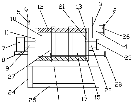
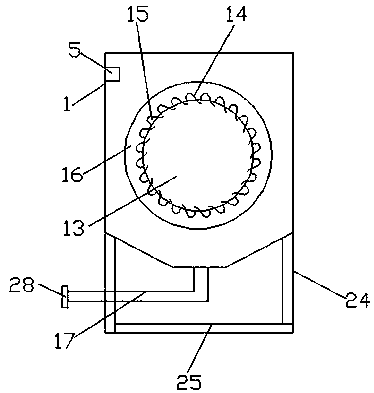
[0026] see Figure 1-3 , according to an embodiment of the present invention, a high-efficiency horizontal solid-liquid separation device includes a main water tank 1, one end of the main water tank 1 is provided with a water inlet pipe 2, and an L baffle 3 is symmetrically provided in the main water tank 1 A water inlet channel 4 is formed between the L baffle plate 3 and the main body water tank 1, and the other end of the main body water tank 1 is provided with a water outlet weir groove 5, and the water outlet weir groove 5 and the main body water tank 1 A groove-shaped water outlet 6 is formed, a drive motor 7 is provided on one side of the main body water tank 1, and a fixing plate 8 is arranged below the drive motor 7, and the fixing plate 8 is fixed on the outer wall of the main body water tank 1. The output end of the driving motor 7 is provided with a rotating shaft 9, and the main water tank 1 is provided with an inertial separation mechanism 10, and the inertial se...

Embodiment 2

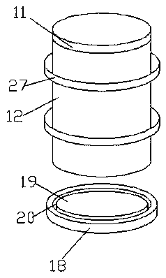
[0029] Such as Figure 1-3 As shown, under the main body water tank 1, supporting legs 24 are symmetrically arranged, and a fixed base 25 is arranged between the supporting legs 24; supporting legs 24 are symmetrically arranged under the main body water tank 1, and a fixed base is arranged between the supporting legs 24 25. It can support and fix the main water tank 1. The water inlet pipe 2 is connected with a water inlet weir groove 26; the water inlet pipe 2 is connected with a water inlet weir groove 26, which can facilitate the mixture to flow into the main water tank 1 through the water inlet weir groove 26. A fixing ring 27 is provided outside the separation bucket 12; One end of the return pipeline 17 is provided with a control valve 28; the control valve 28 is provided at one end of the return pipeline 17, which can conveniently control the switch of the return pipeline 17.

[0030]To sum up, with the help of the above technical solution of the present invention, th...


PUM


Abstract

The invention discloses efficient horizontal solid-liquid separation equipment. The efficient horizontal solid-liquid separation equipment comprises a body water tank, a rotary shaft is arranged at the output end of a driving motor, a separating barrel is arranged on a connecting plate and driven to rotate, a water containing cavity is formed in the separating barrel, multiple arc-shaped flow guiding pieces are arranged on the separating barrel and provided with grooves respectively, flow-guiding layers are arranged on the exteriors of the arc-shaped flow guiding pieces, a flow-back pipeline is arranged in the separating barrel, a rotating disc is arranged at the other end of the separating barrel and provided with a sealed base plate, a sliding groove is formed between the rotating disc and the sealed base plate, a mixture enters the water containing cavity and passes through the arc-shaped flow guiding pieces, water flows out from gaps among the arc-shaped flow guiding pieces, solidis stacked in the grooves of the arc-shaped flow guiding pieces, and therefore the effect of filtering is realized. The efficient horizontal solid-liquid separation equipment has the advantages that the structure is simple, using is convenient, under the effect of centrifugal force, water and solid are separated, the effect of solid-liquid separation is realized, and the working efficiency and separating quality of the solid-liquid separation equipment are improved.

Description

technical field [0001] The invention relates to the technical field of solid-liquid separation equipment, in particular to an efficient horizontal solid-liquid separation equipment. Background technique [0002] Water treatment plants, paper mills, food processing plants, chemical plants, and farms will produce a large amount of microparticle suspensions or solid-liquid mixtures, including semi-finished products from some manufacturers, or waste such as sewage and sludge. The solid content of these materials is only 3-5%, and the liquid content is high and the volume is large. According to relevant data records, if the water content of sludge is reduced from 95% to 80%, its volume will be reduced by 75%; if it is reduced from 80% to 50%, its volume will be reduced by 60%. As far as municipal domestic sludge is concerned, the higher the water content of the sludge, the more difficult it is to carry out final treatment. Only when the water content is lower than 40%, it is s...

Claims


Application Information

Patent Timeline
Patent Type & Authority Applications(China)
IPC IPC(8): B01D36/04
CPCB01D36/045
Inventor 孟令甫金爽张令
Owner ANHUI PUSHI ECOLOGICAL ENVIRONMENT ENG
Why Eureka
Try Eureka