[0030] Embodiments of the present invention are described in detail below, examples of which are shown in the drawings, wherein the same or similar reference numerals designate the same or similar elements or elements having the same or similar functions throughout. The embodiments described below by referring to the figures are exemplary and are intended to explain the present invention and should not be construed as limiting the present invention.
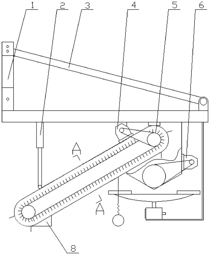
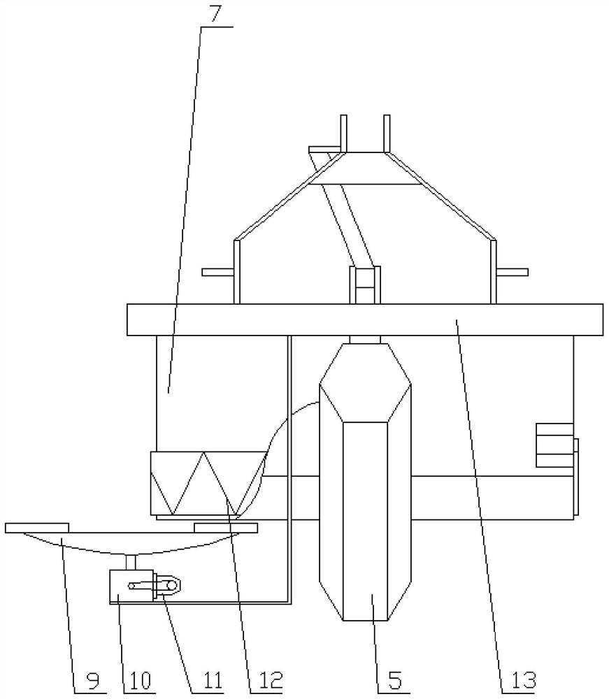
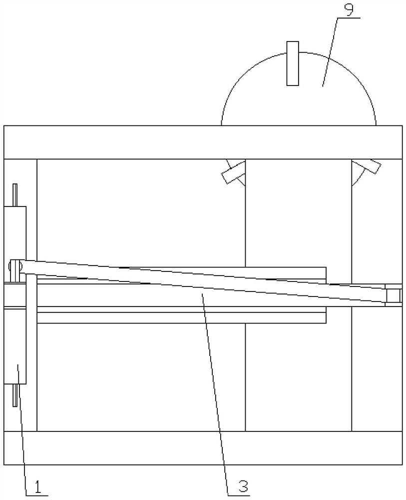
[0031] like Figure 1 to Figure 4 As shown, the present invention provides a farmland ditch cleaning machine, comprising a triangular suspension frame 1, the top of the triangular suspension frame 1 is hinged to one side of the support frame 3, and the other side of the support frame 3 is hinged to the top of the flat plate 13; Boom 2 is installed on one side of the bottom of plate 13 and is connected to the lower part of the outer wall of elevator I5 through boom 2, and the top opening of elevator I5 is connected to the inner wall of soil accumulation box 7; the inside of soil accumulation box 7 is Elevator II 12 is installed, and a discharge opening is provided on one side of the outer wall of the soil accumulation box 7, and a spinner 9 is installed at the bottom of the soil accumulation box 7; the farmland ditch cleaning machine of the present invention uses machines instead of manpower to clean the ditch system. soil accumulation, saving manpower.
[0032] As a preferred embodiment of the present invention, the triangle suspension frame 1 is connected with the central pull rod and the left and right pull rods at the rear of the tractor through the hitch pins and the support points on both sides, and the cleaning can be adjusted by adjusting the right pull rod screw rod of the tractor. The left and right levels of the cleaning machine can be adjusted by adjusting the central pull rod of the tractor to adjust the front and rear levels of the cleaning machine.
[0033] As a preferred embodiment of the present invention, such as figure 1 As shown, the power input end of the elevator I5 is connected to the power output end of the hydraulic motor I4, and the power input end of the hydraulic motor I4 is connected to the power output end of the power output shaft of the tractor, and the tractor power output shaft drives the hydraulic pressure The motor I4 provides power output as the power source of the elevator I5.
[0034] As a preferred embodiment of the present invention, such as figure 1 As shown, a small boat body 8 is installed at the bottom of the elevator I5, and the small boat body 8 is in the shape of a trapezoid, fits the shape of the ditch system, and guides the elevator I5.
[0035] As a preferred embodiment of the present invention, such as figure 2 As shown, the power input end of the elevator II12 is connected to the power output end of the hydraulic motor II6, and the power input end of the hydraulic motor II6 is connected to the power output end of the power oil of the shunt oil pipe of the tractor. Oil pipe power oil drives the hydraulic motor II6 to work, and provides power for the elevator II12 in the soil accumulation box 7.
[0036] As a preferred embodiment of the present invention, such as figure 2 As shown, the power input end of the spinner 9 is connected to the power output end of the hydraulic motor III11 through the gearbox 10, and the power input end of the hydraulic motor III11 is connected to the power output end of the power oil of the shunt oil pipe of the tractor. The power oil in the shunt oil pipe drives the hydraulic motor III11 to work, provides power for the gear box 10, and drives the spinner 9 to work.
[0037] As a preferred embodiment of the present invention, such as Figure 4 As shown, the elevator I5 is in a hexagonal shape with a stable structure and is convenient for soil retrieval.
[0038] The invention also provides an application method of the farmland ditch clearing machine, which is structurally realized by four parts: a suspension part, a transmission part, a soil fetching part and a soil sending part.
[0039] The working principle of the present invention is: the farmland ditch cleaning machine is structurally composed of four parts: a suspension part, a transmission part, a soil fetching part and a soil sending part, wherein the suspension part adopts a 3-point suspension design, and the triangular suspension The sub and the support points on both sides are connected with the central pull rod and the left and right pull rods at the rear of the tractor. The left and right levels of the cleaning machine can be adjusted by adjusting the right pull rod screw of the tractor, and the front and rear levels of the cleaning machine can be adjusted by adjusting the central pull rod of the tractor; the transmission part is mainly It is divided into three routes. The first route is driven by the power output shaft of the tractor to drive the hydraulic motor Ⅰ4 to provide power output, which is used as the power source of the elevator Ⅰ5. The second route is driven by the power oil of the shunt oil pipe to drive the hydraulic motor Ⅱ6 to work for the soil accumulation box 7. The power is provided by the elevator II12, and the third route is to drive the hydraulic motor III11 to work by the power oil of the shunt oil pipe, which provides power for the gearbox 10 and drives the spinner 9 to work; the main action of the soil retrieval part is completed by the elevator I5, and the lifting Elevator I5 is in the shape of a hexagon. There is a soil intake port at the bottom of Elevator I5, which is close to the ditch surface. Transported to the soil accumulation box 7, in addition, the small boat body 8 is in the shape of a trapezoid, fits the shape of the ditch system, and guides the elevator I5; The soil at the bottom of the soil accumulation box 7 falls onto the top of the spinning disk 9 along with the operation of the elevator II 12, and the rotation of the spinning disk 9 drives the soil to throw to the borders on both sides.
[0040]In the description of the present invention, it should be understood that the terms "center", "longitudinal", "transverse", "length", "width", "thickness", "upper", "lower", "front", "rear" ", "Left", "Right", "Vertical", "Horizontal", "Top", "Bottom", "Inner", "Outer", "Clockwise", "Counterclockwise", etc. Based on the orientation or positional relationship shown in the drawings, it is only for the convenience of describing the present invention and simplifying the description, and does not indicate or imply that the referred device or element must have a specific orientation, be constructed and operated in a specific orientation, and therefore cannot be construed as a limitation of the invention.
[0041] In the description of this specification, descriptions referring to the terms "one embodiment", "some embodiments", "example", "specific examples", or "some examples" mean that specific features described in connection with the embodiment or example , structure, material or characteristic is included in at least one embodiment or example of the present invention. In this specification, the schematic representations of the above terms should not be understood as necessarily referring to the same embodiment or example. Furthermore, the specific features, structures, materials or characteristics described may be combined in any suitable manner in any one or more embodiments or examples. In addition, those skilled in the art can combine and combine different embodiments or examples described in this specification.
[0042] The above embodiments are only to illustrate the technical ideas of the present invention, and can not limit the protection scope of the present invention with this. All technical ideas proposed in accordance with the present invention, any changes made on the basis of technical solutions, all fall within the protection scope of the present invention. Inside.