Self-calibrating apacitor-type liquid level gauge

A capacitive liquid level, self-calibration technology, applied in the direction of the liquid level indicator for physical variable measurement, can solve the problems of unsatisfactory measurement accuracy and long-term stability, poor stability, etc., to achieve good long-term stability, The effect of high measurement accuracy and convenient installation and use

Inactive Publication Date: 2003-10-01
赵明旭
View PDF4 Cites 0 Cited by
  • Summary
  • Abstract
  • Description
  • Claims
  • Application Information

AI Technical Summary

Problems solved by technology

Some have mechanical parts that move frequently, and some have poor stability. Most of them are affected by changes in physical parameters such as the

Method used


Image

  • Self-calibrating apacitor-type liquid level gauge
  • Self-calibrating apacitor-type liquid level gauge
  • Self-calibrating apacitor-type liquid level gauge

Examples


Embodiment Construction

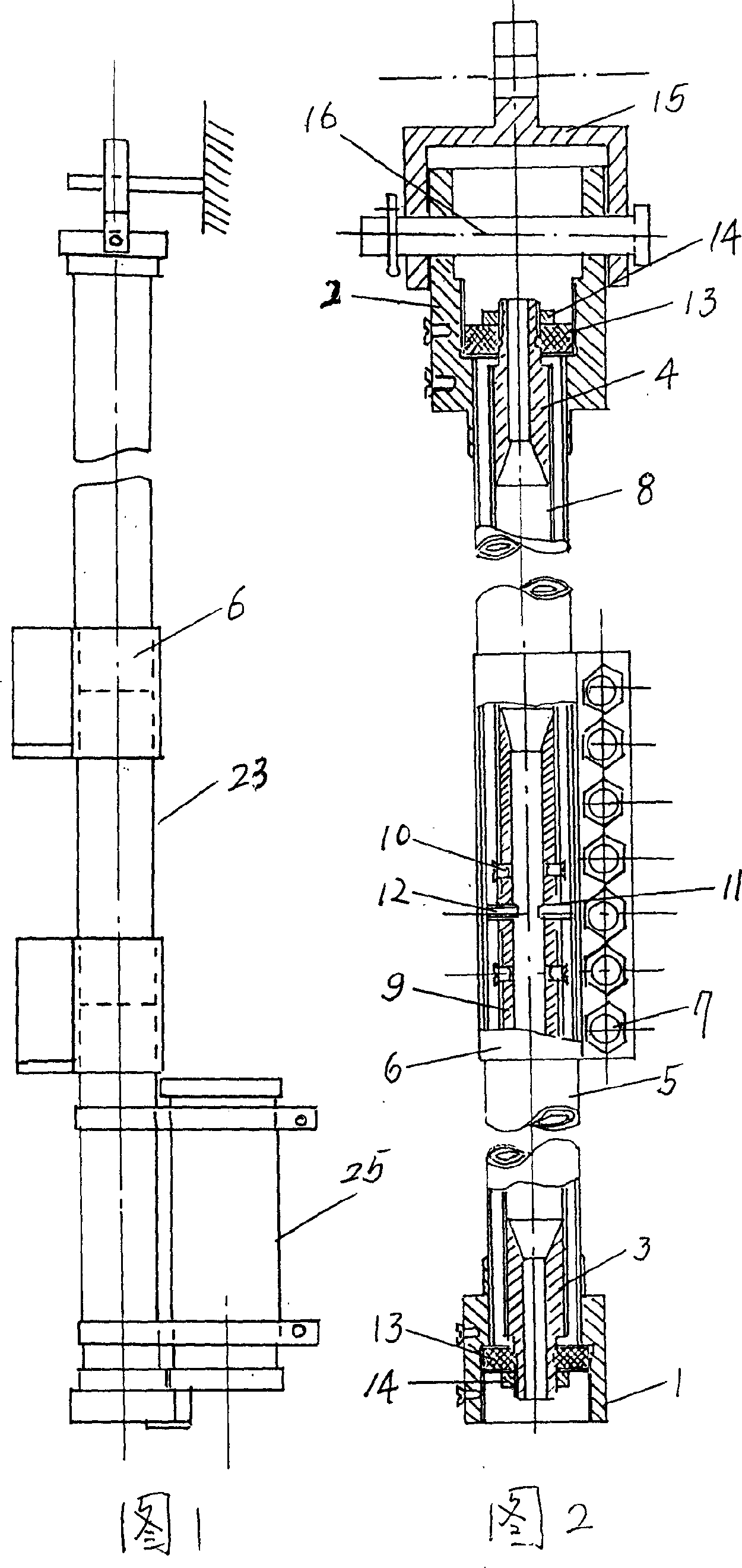
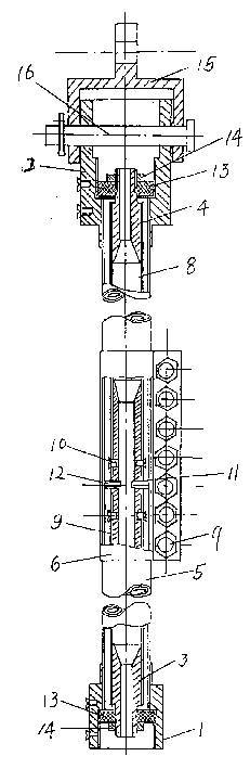
[0026] The self-calibrating capacitive liquid level gauge is a coaxial capacitive sensor composed of a calibration sensor and a measuring sensor. The measuring sensor includes an outer tube, an inner tube, a bottom joint 1 of the outer tube, a top joint 2 of the outer tube, a bottom joint 3 of the inner tube, and a top joint 4 of the inner tube.

[0027] The outer tube is made up of multi-section short outer tubes 5 butt joints, and clips 6 are sleeved at the joints of every two short outer tubes 5, and the two ends of the clips 6 are fixedly connected by clip screws 7 to clamp the joints. The upper end of the outer pipe bottom joint 1 is sleeved on the lower end of the outer pipe, and is firmly welded with the outer pipe. The lower end of the outer pipe top joint 2 is sleeved on the upper end of the outer pipe, and is firmly welded with the outer pipe.

[0028] The inner tube is composed of multiple short inner tubes 8 connected, and at the joint of every two short inner tub...


PUM


Abstract

A self-calibrating capacitor-type liquid level gauge has measuring sensor and calibrating sensor under the former. Said measuring sensor is composed of inner and outer tubes formed by linking more short tubes together, and respectively having top and bottom joints. Said calibrating sensor consists of inner, middle and outer tubes and their top and bottom caps. It can automatically compensate the change in temp, pressure and environment, having high precision and stability.

Description

(1) Technical field [0001] The invention belongs to a measuring device for liquid level height (2) Background technology [0002] At present, the measurement of the liquid level in many liquid storage tanks in China still adopts manual methods, which is not only inconvenient, but also has a great risk, and the measurement is not timely, and it cannot realize long-distance cluster automatic measurement and control, which is not suitable for requirements of modern management. For high-temperature and high-pressure storage tanks, toxic and harmful media cannot be achieved manually. [0003] There are many kinds of automatic side gauge liquid level gauges available on the market now, including products with various principles such as float ball type, pressure sensor type, laser type, and ultrasonic type. Some have mechanical parts that move frequently, and some have poor stability. Most of them are affected by changes in physical parameters such as the temperature and density ...

Claims


Application Information

Patent Timeline
IPC IPC(8): G01F23/26
Inventor 赵明旭
Owner 赵明旭
Why Eureka
Try Eureka