Lens and lamp with lens

A lens and lamp technology, applied in the field of lighting, can solve the problems of more severe scattering and poor uniformity of illumination, and achieve the effect of large irradiation area and uniform light output

Pending Publication Date: 2021-01-29
SELF ELECTRONICS CO LTD
View PDF0 Cites 0 Cited by
  • Summary
  • Abstract
  • Description
  • Claims
  • Application Information

AI Technical Summary

Problems solved by technology

According to the law of light irradiation, compared with the irradiated area with a shorter irradiated distance, the farther the irradiated distance of light, the more severe the scattering,

Method used


Image

  • Lens and lamp with lens
  • Lens and lamp with lens
  • Lens and lamp with lens

Examples


Embodiment Construction

[0027] Specific embodiments of the present invention will be described in further detail below based on the accompanying drawings. It should be understood that the description of the embodiments of the present invention here is not intended to limit the protection scope of the present invention.

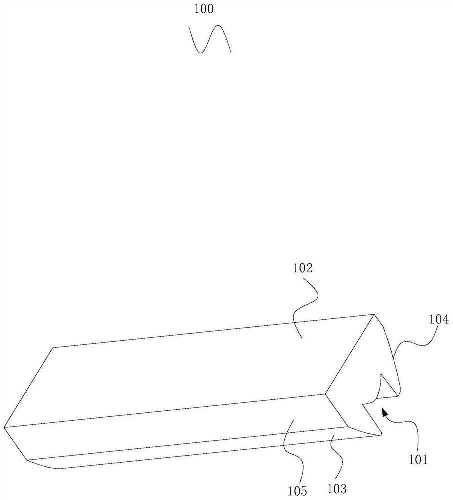
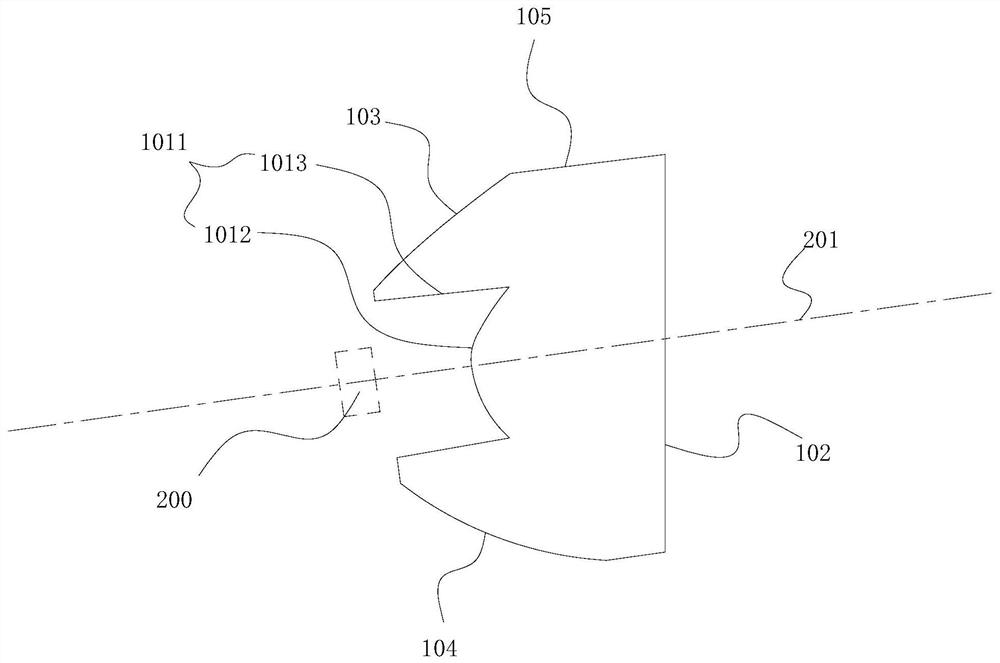
[0028] Such as Figure 1-5 As shown, the lens 100 of this embodiment is strip-shaped, and the strip-shaped lens is easy to manufacture and is suitable for strip lamps, and can be used for light distribution corresponding to multiple point light sources. In order to facilitate manufacture, the shape along the length direction is the same , can be produced by extrusion or injection molding. The lens 100 of this embodiment is surrounded by a top surface, a bottom surface and two sides, wherein the bottom surface of the lens 100 is the light entrance surface 101, the top surface of the lens 100 is the first light exit surface 102, and the lens 100 One side is at least partly the first ...


PUM


Abstract

The invention discloses a lens. The lens is in a long strip shape, the bottom face of the lens is a light inlet face, the top face of the lens is a first light outlet face, at least part of one side of the lens is a first total reflection face, at least part of the other side of the lens is a second total reflection face, and a light source arrangement position with a main optical axis is arrangedon the outer side of the light inlet face. In the cross section of the lens, the main optical axis penetrates through the middle area of the light inlet face and the first light outlet face, part oflight, close to the main optical axis, in the lens is directly emitted out through the first light outlet face, part of light, away from the main optical axis, in the lens is totally reflected by thesecond total reflection face and the first total reflection face and then is emitted out through the first light outlet face, a second light outlet face located between the first total reflection faceand the first light outlet face is arranged on the side, provided with the first total reflection face, of the lens, and a part of light, far away from the main optical axis, in the lens is directlyemitted through the second light outlet face.

Description

technical field [0001] The invention relates to the technical field of lighting, in particular to a lens and a lamp with the lens. Background technique [0002] In the context of energy saving and environmental protection, LED lamps are more and more used in the fields of home and commercial lighting because of their high light extraction efficiency and good light-gathering performance. At the same time, people are constantly pursuing better lighting effects, so they also hope that LED lamps can meet various lighting needs. Especially in the case of large-area and long-distance irradiation, it is desirable to make the illuminance of the irradiated area as uniform as possible. Since the light output effect of the LED chip cannot meet the lighting requirements, it is necessary to carry out secondary optical design through lens cooperation to meet specific light distribution requirements. According to the law of light irradiation, compared with the irradiated area with a clos...

Claims


Application Information

Patent Timeline
IPC IPC(8): F21K9/69F21V5/04F21S4/20F21Y103/10F21Y115/10
CPCF21V5/04F21S4/20F21K9/69F21Y2103/10F21Y2115/10
Inventor 何祖平刘小云陈东杨君
Owner SELF ELECTRONICS CO LTD
Why Eureka
Try Eureka