
Display device

A display device and display function technology, which is applied in the directions of electrical components, diodes, and electric solid-state devices, etc., can solve the problems of uneven display of display panels.

Pending Publication Date: 2021-01-29
YUNGU GUAN TECH CO LTD
View PDF14 Cites 1 Cited by
  • Summary
  • Abstract
  • Description
  • Claims
  • Application Information

AI Technical Summary

Problems solved by technology

[0004] However, in the existing display devices for photosensitive fingerprint recognition, there is a problem of uneven display on the display panel.

Method used


Image

  • Display device
  • Display device
  • Display device

Examples


Embodiment Construction

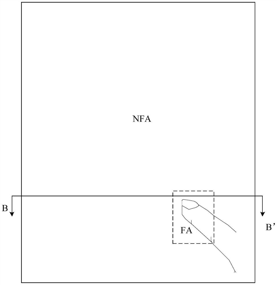
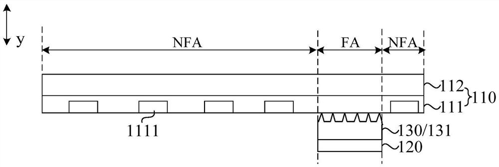
[0028] The present invention will be further described in detail below in conjunction with the accompanying drawings and embodiments. It should be understood that the specific embodiments described here are only used to explain the present invention, but not to limit the present invention. In addition, it should be noted that, for the convenience of description, only some structures related to the present invention are shown in the drawings but not all structures.

[0029] As mentioned in the background, in the existing display devices for optical fingerprint recognition, there is a problem of non-uniform display on the display panel. The inventors have found through research that the reason for the above problems is that the existing display devices for light-sensitive fingerprint recognition usually include a display function layer for display, and the display function layer usually includes a pixel circuit for driving a light-emitting device to emit light. The circuit incl...


PUM


Abstract

The invention discloses a display device. The display device comprises: a display function layer which comprises a thin film transistor array and a light-emitting device layer located at one side of the thin film transistor array; a light sensing device arranged on the side, away from the light-emitting device layer, of the thin film transistor array and located in a fingerprint recognition area;and an optical collimation structure layer arranged between the light sensing device and the display function layer, wherein the optical collimation structure layer comprises an optical collimation structure, the optical collimation structure is arranged in the fingerprint recognition area, the optical collimation structure corresponds to the light sensing device in the thickness direction of thedisplay device, and the surface of the side, close to the display function layer, of the optical collimation structure comprises a micro-nano structure array. According to the display device providedby the embodiment of the invention, the intensity of the irradiated light of each thin film transistor channel in the display function layer is relatively consistent, the performance of the thin filmtransistors can be relatively consistent, the brightness of the light emitting device can be relatively consistent, and the display uniformity of the display panel is further improved.

Description

technical field [0001] Embodiments of the present invention relate to the field of display technologies, and in particular, to a display device. Background technique [0002] With the development of display technology, under-screen recognition technology has become one of the main fingerprint recognition technologies. [0003] Among the existing under-screen fingerprint recognition technologies, light-sensitive fingerprint recognition is the main means of implementation. This technology relies on the local strong light emitted by the display screen to transmit the user's fingerprint information to the fingerprint optical sensor located under the display module, and the sensor converts the optical signal with fingerprint information into an electrical signal for identification. [0004] However, in the existing display devices for photosensitive fingerprint recognition, there is a problem of non-uniform display on the display panel. Contents of the invention [0005] The ...

Claims


Application Information

Patent Timeline
Patent Type & Authority Applications(China)
IPC IPC(8): H01L27/32
CPCH10K59/00H10K59/50H10K59/40H10K59/12
Inventor 赵东方
Owner YUNGU GUAN TECH CO LTD
Learn More