
Automatic wire harness implantation system, method and controller

An automatic line and planting technology, which is applied to the assembly/disassembly of lines/collector parts, vehicle connectors, contacts, etc., can solve the problems of interpolation failure, poor connector model compatibility, and poor interpolation effect, etc., to achieve Accurate planting, improving the quality of planting and improving production efficiency

Active Publication Date: 2021-01-29
季华科技有限公司
View PDF9 Cites 5 Cited by
  • Summary
  • Abstract
  • Description
  • Claims
  • Application Information

AI Technical Summary

Problems solved by technology

[0003] At present, this interpolation operation is generally completed by interpolation equipment. The existing interpolation equipment is usually used independently by a single machine. The connector is fixed on the machine by manual operation. The insertion hole of the connector is oriented horizontally. Insert it into the socket corresponding to the connector in the horizontal direction. After each interpolation, you need to manually replace the next connector to be plugged in, so it is difficult to integrate with the factory automated production line system
Furthermore, the interpolation position is fixed by the system preset, and the connector models (mainly different numbers of plug holes and different shapes of plug holes) have poor compatibility, and the interpolation effect cannot be guaranteed. For example, for flat terminals, the corresponding plug The shape of the hole is also flat. Compared with the cylindrical terminal, it needs to meet a certain angle with the insertion hole to be able to align correctly, that is, the outer contour line of the terminal of the wire and the insertion of the connector. Only when the contour lines of the inner walls of the connecting holes coincide, the terminal can be inserted into the connecting hole correctly; when the angle of the terminal relative to the connecting hole deviates, because the system cannot dynamically correct it, the interpolation effect of the wire terminal becomes poor, or even fails. , it is difficult to realize automatic production

Method used


Image

  • Automatic wire harness implantation system, method and controller
  • Automatic wire harness implantation system, method and controller
  • Automatic wire harness implantation system, method and controller

Examples


Embodiment Construction

[0033] Embodiments of the present invention are described in detail below, examples of which are shown in the drawings, wherein the same or similar reference numerals denote the same or similar elements or elements having the same or similar functions throughout. The embodiments described below by referring to the figures are exemplary only for explaining the present invention and should not be construed as limiting the present invention.

[0034] In describing the present invention, it should be understood that the terms "center", "longitudinal", "transverse", "length", "width", "thickness", "upper", "lower", "front", " Orientation indicated by rear, left, right, vertical, horizontal, top, bottom, inside, outside, clockwise, counterclockwise, etc. The positional relationship is based on the orientation or positional relationship shown in the drawings, which is only for the convenience of describing the present invention and simplifying the description, rather than indicating ...


PUM


Abstract

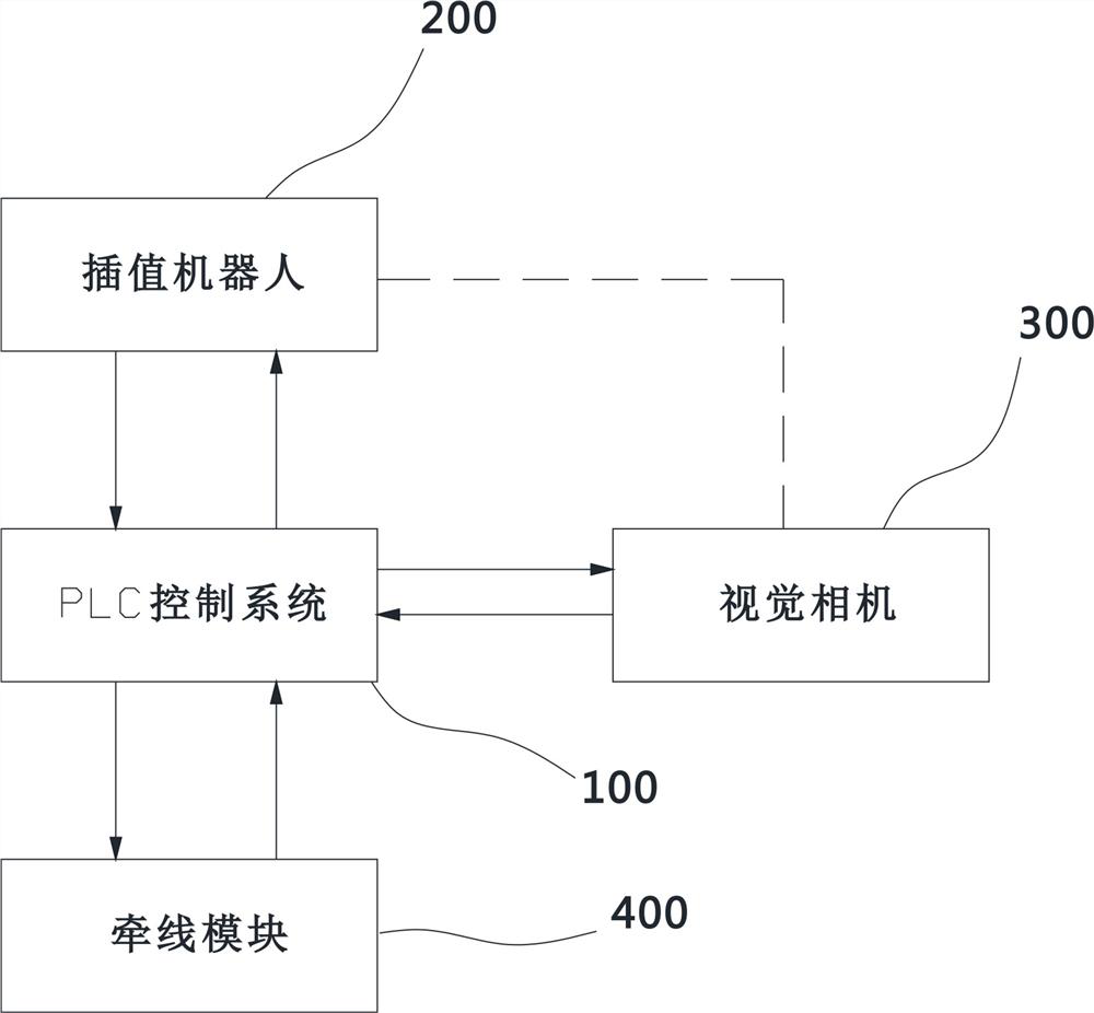
The invention discloses an automatic wire harness implantation system and method and a controller to implant a wire of a wire harness into a connector. The implantation system comprises: a PLC controlsystem, an implantation robot and a visual camera; the visual camera is used for acquiring image information of at least one connector and acquiring first position information and first rotation angle information of the connector according to the image information; and the PLC control system is used for controlling the implantation robot to insert the terminal of the wire into the corresponding insertion hole of the connector according to the first position information and the first rotation angle information of the connector. The implantation method comprises the following steps: A, acquiring first position information and first rotation angle information of the connector; and B, according to the first position information and the first rotation angle information of the connector, controlling the implantation robot to insert the terminal of the wire into a corresponding insertion hole of the connector. According to the invention, automatic work of wire harness implantation is realized, and the implantation work of the wire terminals can be precisely carried out.

Description

technical field [0001] The invention belongs to the technical field of automobile wire harness production, and in particular relates to an automatic wire harness insertion system, method and controller. Background technique [0002] The automotive wiring harness is a circuit network formed by multiple sets of wiring harnesses connected through connectors. The connection between the wiring harness and the connector is completed by inserting the operation, that is, inserting the terminals at both ends of the wire harness into the socket hole of the connector. [0003] At present, this interpolation operation is generally completed by interpolation equipment. The existing interpolation equipment is usually used independently by a single machine. The connector is fixed on the machine by manual operation. The insertion hole of the connector is horizontal, and the interpolation direction is the horizontal direction, that is, the terminal It is inserted into the socket correspondin...

Claims


Application Information

Patent Timeline
Patent Type & Authority Applications(China)
IPC IPC(8): H01R43/00H01R43/20H01R43/26
CPCH01R43/00H01R43/20H01R43/26H01R2201/26
Inventor 陶红保邹才威
Owner 季华科技有限公司
Learn More