
Intelligent cooling and heat dissipation device for data machine room

A technology for data computer rooms and heat dissipation devices, which is applied in data processing centers, cooling/ventilation/heating transformation, special buildings, etc., and can solve the problem of not being able to realize rapid heat dissipation inside the computer room and equipment in the computer room, easily occupying the internal area of ​​the computer room, and affecting the cooling device Use and other problems to achieve good moisture-proof, improve heat dissipation effect, and improve service life

Active Publication Date: 2021-01-29
深圳市华电联合建设工程有限公司
View PDF8 Cites 0 Cited by
  • Summary
  • Abstract
  • Description
  • Claims
  • Application Information

AI Technical Summary

Problems solved by technology

[0004] In order to overcome the above-mentioned technical problems, the object of the present invention is to provide an intelligent cooling and heat dissipation device for the data computer room, which can effectively solve the problem that the existing intelligent cooling and heat dissipation devices for the data computer room are basically placed directly in the data computer room , easy to occupy the internal area of ​​the computer room; the heat dissipation effect of the existing intelligent cooling and heat dissipation devices used in the data computer room is general, and cannot realize the rapid heat dissipation of the interior of the computer room and the equipment in the computer room; the existing intelligent cooling and heat dissipation devices used in the data computer room lack dust-proof measures , technical issues that affect the use of heat sinks

Method used


Image

  • Intelligent cooling and heat dissipation device for data machine room
  • Intelligent cooling and heat dissipation device for data machine room
  • Intelligent cooling and heat dissipation device for data machine room

Examples


Embodiment Construction

[0031] The technical solutions in the embodiments of the present invention will be clearly and completely described below in conjunction with the embodiments of the present invention. Apparently, the described embodiments are only some of the embodiments of the present invention, not all of them. Based on the embodiments of the present invention, all other embodiments obtained by persons of ordinary skill in the art without creative efforts fall within the protection scope of the present invention.

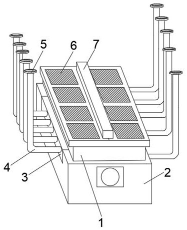
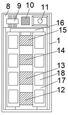
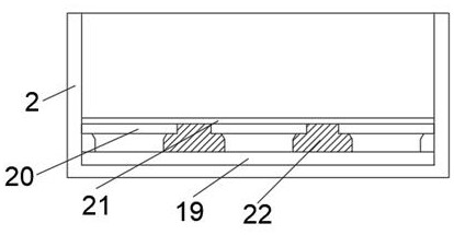
[0032] Such as Figure 1-5 As shown in the figure, an intelligent cooling and heat dissipation device for a data center includes a cooling box 1, a built-in box 2 is sleeved on the outside of the cooling box 1, and connecting plates 3 are installed on both sides of the built-in box 2 near the top, A number of diffuser tubes 4 are installed on both side walls of the radiator box 1 and the embedded box 2, and the top of each diffuser tube 4 is connected with a flange 5, and the top ...


PUM


Abstract

The invention discloses an intelligent cooling and heat dissipation device for a data machine room. The device comprises a heat dissipation box, an outer side of the heat dissipation box is provided with an embedded box, connecting plates are installed at the positions, close to the top, of the two sides of the embedded box, a plurality of diffusion pipes penetrate through the heat dissipation boxand the two side walls of the embedded box, and the top end of each diffusion pipe is connected with a flange plate; a plurality of sets of air supply windows are formed in the top of the heat dissipation box, a protection box is arranged in the middle of the top of the heat dissipation box, a control box is arranged at the position, close to one end, of the interior of the heat dissipation box,and a temperature sensor, a DSP and a PLC are sequentially arranged on the inner side of the control box; and an air inlet fan, a compressor, a cooler and an air exhaust fan are sequentially installedin the heat dissipation box from front to back, and one end of the air exhaust fan is connected with a connecting pipe. According to the invention, an occupied area of the machine room can be effectively reduced, meanwhile, a heat dissipation range is wide, and a good dustproof effect is achieved.

Description

technical field [0001] The invention belongs to the field of heat dissipation devices, in particular to a heat dissipation device for a computer room, and more specifically to an intelligent cooling and heat dissipation device for a data computer room. Background technique [0002] During the operation of the data computer room, due to the continuous operation of the equipment, a large amount of heat will be generated. Therefore, in order to ensure the normal operation of the entire computer room, it is necessary to use a cooling device to dissipate heat. The intelligent cooling device can monitor the temperature dynamics of the computer room in real time, and then carry out intelligent cooling. . [0003] The existing intelligent cooling and heat dissipation devices for data computer rooms have certain disadvantages in use. The existing intelligent cooling and heat dissipation devices for data computer rooms are basically placed directly in the data computer room, which eas...

Claims


Application Information

Patent Timeline
Patent Type & Authority Applications(China)
IPC IPC(8): H05K7/20E04H5/00
CPCH05K7/20745H05K7/20836E04H5/00E04H2005/005
Inventor 石建羽石兴源
Owner 深圳市华电联合建设工程有限公司
Learn More