

Indoor unit for air conditioner
A technology of air conditioner and indoor unit, which is applied in air conditioning system, space heating and ventilation details, space heating and ventilation, etc. It can solve problems such as inability to purify air efficiently, and achieve the effect of maintaining cycle performance
- Summary
- Abstract
- Description
- Claims
- Application Information
AI Technical Summary
Problems solved by technology
Method used
Image

Examples
no. 1 approach 〕
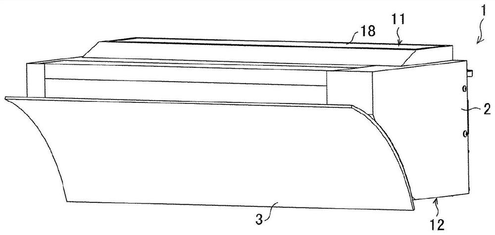
[0040] figure 1 It is a perspective view which shows the appearance of the indoor unit 1 of the air conditioner of this embodiment.
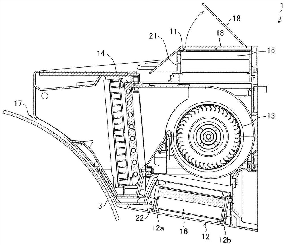
[0041] figure 2 yes figure 1 A longitudinal sectional view of the indoor unit 1 of the air conditioner shown.
[0042] (Outline of indoor unit 1)
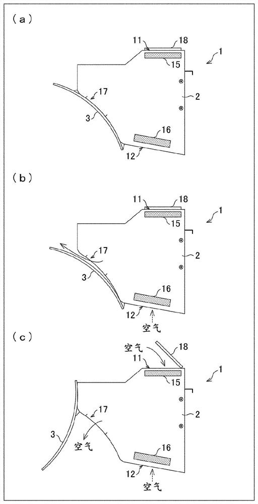
[0043] Such as figure 1 As shown, the indoor unit 1 of the air conditioner is equipped with the air guide plate 3 on the front surface of the indoor unit main body part 2 (main body part). Such as figure 2 As shown, the indoor unit main body 2 has a first suction port 12 (lower suction port) for sucking air in the lower surface, a second suction port 11 (upper suction port) for sucking air in the upper surface, and a blower fan 13 inside. And the heat exchanger 14 has an outlet 17 at the front.
[0044] In addition, the indoor unit 1 has a first filter 16 (first air cleaning filter) that purifies the passing air inside (upper side) of the first suction port 12, and has a first filter 16 (...
Deformed example 1
[0063] As mentioned above, in this embodiment, the case where the indoor unit main body part 2 has the 1st suction port 12 and the 2nd suction port 11 was demonstrated as an example. but, Figure 9 The problems described above also occur similarly when the air inlet provided with the air cleaning filter is provided only on the lower surface of the indoor unit of the air conditioner.
[0064] In addition, the indoor unit 1 is installed at a relatively high position in the air-conditioned space, such as near the ceiling. Therefore, by providing the first suction port 12 provided with the first filter 16 on the lower surface of the indoor unit 1, compared with the indoor unit of the conventional air conditioner in which the air purification filter is only provided on the upper surface of the indoor unit, , can improve the air purification effect, and can increase the intake air volume of the air.
[0065] Therefore, the present embodiment can also be applied to a case where only ...
Deformed example 2
[0067] In addition, in this embodiment, the case where the 1st filter 16 and the 2nd filter 15 are HEPA filters, for example was demonstrated as an example. However, the present embodiment is not limited thereto, the first filter 16 and the second filter 15 may be ULPA (Ultra Low Penetration Air Filter: ultra-long adjustable filter), the first filter 16 and the second filter One of the 15 can also be a HEPA filter, and the other can also be a ULPA filter. In addition, at least one of the first filter 16 and the second filter 15 may use an air cleaning filter other than a HEPA filter called a high-performance filter.
[0068] For example, the size of the dust (particle size) that can be collected by the ULPA filter is smaller than that of the HEPA filter, and the collection rate of fine dust (air cleaning rate) is high. On the other hand, the ULPA filter is more difficult for air to pass through than the HEPA filter, and the air volume is smaller. The greater the amount of su...
PUM
 Abstract
Description
Claims
Application Information