Directional toppling auxiliary device for forestry cedar felling

A technology for dumping auxiliary devices and fir trees, which can be used in forestry, agriculture, applications, etc., and can solve problems such as trees jamming saw blades, labor consumption, and motor damage

Pending Publication Date: 2021-02-02
来利冰
View PDF10 Cites 5 Cited by
  • Summary
  • Abstract
  • Description
  • Claims
  • Application Information

AI Technical Summary

Problems solved by technology

[0002] At present, in logging operations, it is more and more common for people to use saws. People use saws to saw trees to make furniture. Most of the chainsaws used in the market are used for logging. There are also some small trees that are manually pulled by saw blades, but In the process of sawing trees, both the electric saw and the manual saw blade will appear to be pressed against the saw blade by the tree. When the saw blade of the electric saw is pressed, the mo

Method used


Image

  • Directional toppling auxiliary device for forestry cedar felling
  • Directional toppling auxiliary device for forestry cedar felling
  • Directional toppling auxiliary device for forestry cedar felling

Examples


Embodiment 1

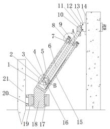
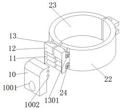
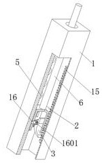
[0029] refer to Figure 1-5 , a forestry fir tree felling directional dumping auxiliary device, including a wooden stake 21 nailed near the root of the side of the tree to be felled to avoid falling, a mother bucket 1 with an upward opening and a rectangular parallelepiped structure, and two hinged hoops One 22 and clamp two 23, one end of clamp one 22 and two clamps 23 away from the hinge point are reserved with projections 12, and the side of the two projections 12 far away from the trunk is provided with top tooth grooves 11 near the middle The upper surface and the lower surface of the two projections 12 are provided with notches 13 coaxially distributed, and fastening bolts 24 are fixed between the gaps 13 between the two projections 12, and the outer wall of the stake 21 is close to the bottom. A bearing holder 19 is provided at the end, and the upper and lower surfaces of the bearing holder 19 are respectively clamped with mutually symmetrical tapered roller bearings 17...

Embodiment 2

[0038] refer to figure 1 and Figure 5 , a forestry fir felling directional dumping auxiliary device. Compared with Embodiment 1, this embodiment also includes two insertion rings 901 that are symmetrical to each other at the top of the inner threaded pipe 7 near the edge, and the two insertion rings 901 are Insertion rods 9 are inserted into the rings 901 .

[0039] Wherein, the opposite ends of the two insertion rods 9 are hinged with a folding rod 8, so that when the inner threaded pipe 7 needs to be rotated during use, if the resistance is too large, only the folding rod 8 needs to be straightened, thereby increasing the power arm. The length makes the rotation more labor-saving.


PUM


Abstract

The invention belongs to the technical field of forestry felling, and particularly relates to a directional toppling auxiliary device for forestry cedar felling. The directional toppling auxiliary device aims at solving the problem that lumberjacks are injured inattentively due to the fact that fixing devices inserted into the ground can be suddenly pulled up once trees fall down due to the fact that one supporting frame is arranged in an existing lumbering auxiliary toppling device mostly and the bottom end of the supporting frame is inserted into soil. According to the scheme, the directional toppling auxiliary device comprises a timber pile nailed near the root of one side of a tree to be fallen and for preventing toppling, a main barrel with an upward opening and of a cuboid structurein the overall appearance, a hoop I and a hoop II, wherein the hoop I and the hoop II are hinged together. According to the directional toppling auxiliary device for forestry cedar felling, when the tree needs to be jacked and supported in the using process, firstly, only a tree trunk needs to be held through the hoop I and the hoop II, then the tree trunk can be propped against only by adjustinga transmission screw rod, and at the moment that the tree trunk is cut, a propping block, the hoop I and the hoop II can be automatically separated from a supporting device, so that the supporting device is prevented from being pulled away together, and the safety of a device is improved.

Description

technical field [0001] The invention relates to the technical field of forestry logging, in particular to an auxiliary device for directional dumping of forestry fir trees. Background technique [0002] At present, in logging operations, it is more and more common for people to use saws. People use saws to saw trees to make furniture. Most of the chainsaws used in the market are used for logging. There are also some small trees that are manually pulled by saw blades, but In the process of sawing trees, both the electric saw and the manual saw blade will appear to be pressed against the saw blade by the tree. When the saw blade of the electric saw is pressed, the motor will be damaged; when the saw blade is manually pulled and pressed, It consumes a lot of workers' energy. [0003] There are also many problems that trees will fall when sawing trees. Sometimes it is okay to fall to a place where there are no people. It can fall in the direction specified by itself, and the s...

Claims


Application Information

Patent Timeline
IPC IPC(8): A01G23/099
CPCA01G23/099
Inventor 来利冰
Owner 来利冰
Why Eureka
Try Eureka