Continuous fastener tape turning-around and cutting-off unit and zipper manufacturing equipment adopting continuous fastener tape turning-around and cutting-off unit

A technology for cutting units and zipper tapes, applied in the direction of application, sliding fastener components, fasteners, etc., can solve the problems that cannot meet the needs of full automation of zipper manufacturing equipment, and have not been seen.

Pending Publication Date: 2021-02-02
SHENZHEN GUANZHONG TECH CO LTD
View PDF0 Cites 2 Cited by
  • Summary
  • Abstract
  • Description
  • Claims
  • Application Information

AI Technical Summary

Problems solved by technology

However, in the processes of zipper pasting, punching, dimensioning, forming the bottom stop or forming the box plug, the bottom end is used as the head to move forward, while in the processes of zipper threading, forming the top stop, etc., it is the upper end. For a long time, the connection between the processes of zipper glueing, punching, dimensioning, forming bottom stop or forming square pin and zipper threading, forming top stop and other processes has been done manually. The U-turn of the zipper is done manually, so it is a pity that there is no automatic connection between the processes of zipper glueing, punching, dimensioning, forming bottom stop or forming square pin with the processes of zipper threading and forming top stop. There is no automatic U-turn unit, and there is no zipper manufacturing pre-production equipment that can be automatically connected with zipper threading, forming top stop, etc., or can be connected with zipper glue, punching, dimensioning, forming bottom stop or forming square pins A kind of post-zipper manufacturing equipment that automatically connects, and there is no fully automated equipment before and after zipper manufacturing, which is increasingly unable to meet people's needs for fully automated zipper manufacturing equipment.

Method used


Image

  • Continuous fastener tape turning-around and cutting-off unit and zipper manufacturing equipment adopting continuous fastener tape turning-around and cutting-off unit
  • Continuous fastener tape turning-around and cutting-off unit and zipper manufacturing equipment adopting continuous fastener tape turning-around and cutting-off unit
  • Continuous fastener tape turning-around and cutting-off unit and zipper manufacturing equipment adopting continuous fastener tape turning-around and cutting-off unit

Examples


Embodiment 1

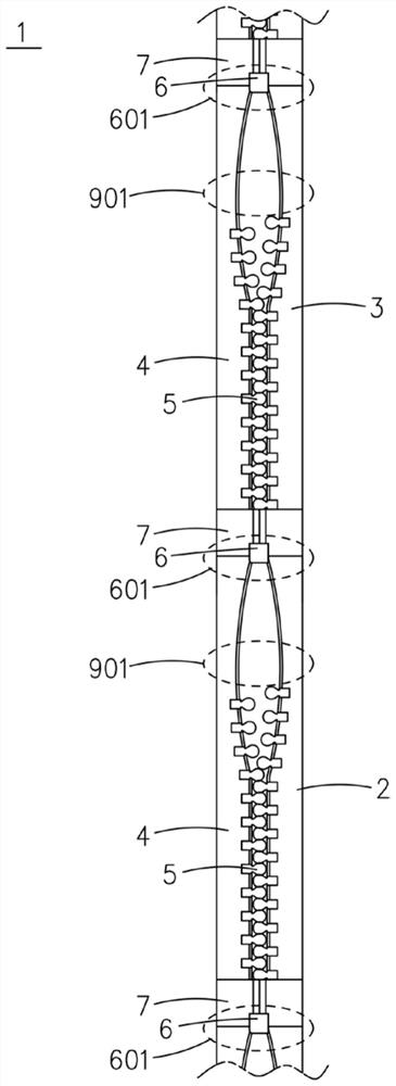
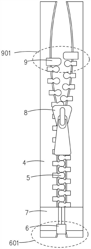
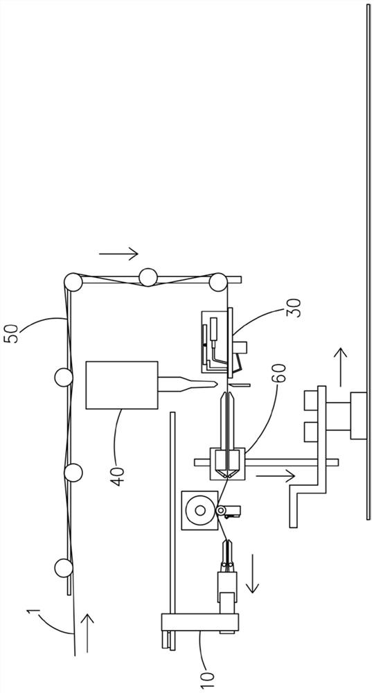
[0046] see image 3 , the continuous zipper tape U-turn of the present invention, cutting unit, comprise the drawstring device 10 that is used to pull the continuous zipper tape 1 to advance, the positioning device 30 that is used for positioning the lower end stop portion 601 of the zipper, is used for the continuous zipper tape 1 The cutting device 40 for cutting between the last upper end stop 901 and the next lower end stop 601, the belt guide device 50 for guiding the continuous zipper tape 1 to turn around, and the zipper for turning around and cutting. Conveying device 60 for delivery.

[0047] see image 3 , 4 , The guide belt device 50 includes a horizontal L-shaped guide wheel bar 51, and a plurality of guide wheels 52 are mounted on the guide wheel bar 51, and the plurality of guide wheels 52 are distributed along the guide wheel bar 51 in a horizontal L-shape. The belt-drawing device 10 is located below the belt-guiding device 50 , and together with the belt-gui...

Embodiment 2

[0052] see Figure 10 , the equipment before the zipper manufacture of the present invention includes a gluing device 110, a punching device 120, a sizing device 130, a box pin forming device 140, and also includes the continuous zipper tape U-turn and cutting unit described in Embodiment 1; Gluing device 110, punching device 120, sizing device 130, box pin forming device 140 are provided with continuous zipper tape U-turn, cutting unit, by gluing device 110, punching device 120, sizing device 130, box pin forming device 140 The manufactured continuous zipper tape 1 enters the tape guide device 50 in the continuous zipper tape U-turn and cutting unit, and then is turned around and cut. The pre-manufacturing equipment of the zipper of the present invention, through the conveying device 60 in the continuous zipper tape U-turning and cutting unit, can realize automatic connection with the zipper head threading, forming top stop and other processes.

Embodiment 3

[0054] see Figure 11 , the post-manufacturing equipment of the zipper of the present invention includes the head-threading device 210, the upper stop forming device 220, the discharge device 230, and also includes the continuous zipper tape U-turn and cutting unit described in Embodiment 1; on the head-threading device 210, the upper Before the forming device 220 and the discharge device 230, the continuous zipper tape U-turn and cutting unit are arranged, and the zipper after the continuous zipper tape U-turn, the cutting unit U-turn, and the cutting passes through the conveying device 60 in the continuous zipper tape U-turn and cutting unit, and enters the The head device 210, and then reaches the top stop forming device 220, the discharge device 230, and carries out the head piercing, forming the top stop and discharging. The post-manufacturing equipment of the zipper of the present invention, through the continuous zipper tape U-turn and the tape guide device 50 in the cu...


PUM


Abstract

The invention discloses a continuous zipper tape turning-around and cutting-off unit which comprises a tape pulling device used for pulling a continuous zipper tape to advance, a positioning device used for positioning a lower end stop part of the zipper and a cutting-off device used for cutting off the continuous zipper tape between an upper end stop part and a lower end stop part; the unit further comprises a tape guiding device is used for guiding the continuous zipper tape to turn around and advance, and a conveying device used for conveying the zipper which turns around and is cut off. The positioning device, the cutting-off device, the conveying device and the zipper tape pulling device are sequentially arranged in the turning advancing direction of the continuous zipper tape. Through the design and application of the continuous zipper tape turning-around and cutting-off unit, the automation degree of the zipper manufacturing equipment is greatly improved, and the requirement ofpeople for zipper manufacturing automation at present can be met.

Description

technical field [0001] The invention relates to the technical field of zipper manufacturing equipment, in particular to a continuous zipper tape turning and cutting unit and zipper manufacturing equipment using the unit. Background technique [0002] Manufacturing a zipper needs to go through many processes, including gluing, punching, dimensioning, forming the bottom stop, forming a square pin, cutting, threading, forming the top stop, and discharging. In the processes of gluing, punching, sizing, forming bottom stop, and forming square pins, the external form of the semi-finished zipper as the processing object is a continuous zipper tape, with the bottom end as the head, moving forward, passing through The gluing device is used to apply glue, the punching device is used to punch holes, the dimensioning device is used to determine the size, the bottom stop forming device is used to form the bottom stop or the box pin forming device is used to form the box pin, and then the...

Claims


Application Information

Patent Timeline
Patent Type & Authority Applications(China)
IPC IPC(8): A44B19/42A44B19/62A44B19/60
CPCA44B19/42A44B19/60A44B19/62
Inventor 吕永平胡应金
Owner SHENZHEN GUANZHONG TECH CO LTD
Why Eureka
Try Eureka