Puncture needle positioning frame

A puncture needle and positioning frame technology, applied in the field of medical devices, can solve problems such as difficult to ensure the puncture needle, increase the difficulty of adjusting the position of the puncture guide, and difficult puncture angle, so as to achieve the effect of ensuring accuracy

Pending Publication Date: 2021-02-02
SHANGHAI KANGLULIAN MEDICAL TECH CO LTD
View PDF1 Cites 1 Cited by
  • Summary
  • Abstract
  • Description
  • Claims
  • Application Information

AI Technical Summary

Problems solved by technology

However, due to human breathing and other actions, the puncture point on the surface of the human body is constantly fluctuating, which not only increases the difficulty of adjusting the position of the puncture guide, but also once the position of the puncture guide is fixed, it is difficult to ensure the puncture guided by it. The needle can accurately penetrate into the puncture point; in addition, the puncture guide in the prior art only plays an auxiliary guiding role. When the puncture needle penetrates into the human body, the doctor needs to hold the front end of the puncture needle to control the needle insertion, and the actual puncture angle is affected by the Due to the influence of the angle of the doctor holding the needle and the direction of force, it is difficult to accurately maintain the set puncture angle

Method used


Image

  • Puncture needle positioning frame
  • Puncture needle positioning frame
  • Puncture needle positioning frame

Examples


no. 1 example

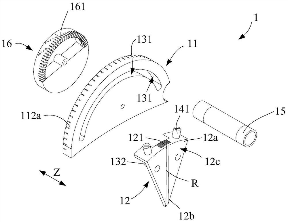
[0076] refer to Figure 2a ~ Figure 2c and combine figure 1 In this embodiment, a puncture needle positioning frame 1 is provided, and the puncture needle positioning frame 1 includes a base 11 and a puncture needle guide member 12 .

[0077]In this embodiment, the base 11 is a fan-shaped base, and the base 11 is arranged around the first axis S; the puncture needle guide 12 is also fan-shaped, and the puncture needle guide 12 is movably arranged on the base 11 . One sector (the first sector 12c) of the puncture needle guide 12 is provided with a needle track R, the needle track R is located in the first plane P1', and the first plane P1' is a plane perpendicular to the first axis S. In this embodiment, the plane where the first fan surface 12c is located is parallel to or coincident with the first plane P1'. In this embodiment, the needle track R is a groove formed on the puncture needle guide 12, but the present invention is not limited to this. In other embodiments, the n...

no. 2 example

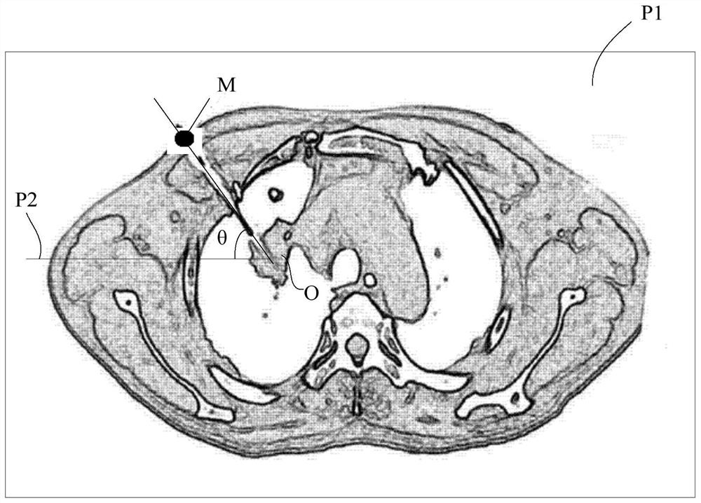
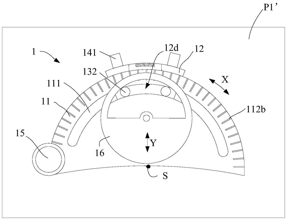
[0103] refer to Figure 3a ~ Figure 3c and combine figure 1 , this embodiment provides a puncture needle positioning frame 1, including: a base 11, the base 11 is arranged around the first axis S; a puncture needle guide 12, which is movably arranged on the base 11; a puncture needle guide 12 is provided with a needle track R, the needle track R is located in the first plane P1', and the first plane P1' is a plane perpendicular to the first axis S. The needle track R extends along the radial direction of the base 11 . When the puncture needle guide 12 moves relative to the base 11 , the needle track R can be driven to move in the circumferential direction of the base 11 . In the working state, the base 11 is fixedly arranged on the surface of the human body through its bottom surface, the first axis S passes through the puncture point M on the surface of the human body, and the first plane P1' coincides with the puncture plane P1.

[0104] The working principle of this embod...

no. 3 example

[0114] refer to Figure 4 and combine figure 1 , this embodiment provides a puncture needle positioning frame 1, including: a base 11, the base 11 is arranged around the first axis S; a puncture needle guide 12, which is movably arranged on the base 11; a puncture needle guide 12 is provided with a needle track R, the needle track R is located in the first plane P1', and the first plane P1' is a plane perpendicular to the first axis S. The needle track R extends along the radial direction of the base 11 . When the puncture needle guide 12 moves relative to the base 11 , the needle track R can be driven to move in the circumferential direction of the base 11 . In the working state, the base 11 is fixedly arranged on the surface of the human body through its bottom surface, the first axis S passes through the puncture point M on the surface of the human body, and the first plane P1' coincides with the puncture plane P1.

[0115] The working principle of this embodiment is simi...


PUM


Abstract

The invention provides a puncture needle positioning frame. The puncture needle positioning frame comprises a base arranged around a first axis, and a puncture needle guide piece which is movably arranged on the base; a needle channel located in a first plane is arranged in the puncture needle guide piece, and the first plane is perpendicular to the first axis; the needle channel extends in the radial direction of the base, and when the puncture needle guide piece moves relative to the base, the needle channel can be driven to move in the circumferential direction of the base, wherein in the working state, the base is fixedly arranged on the surface of a human body through the bottom face of the base, the first axis penetrates through a puncture point on the surface of the human body, andthe first plane coincides with the puncture plane. Through the puncture needle positioning frame provided by the invention, the puncture accuracy can be ensured.

Description

technical field [0001] The invention relates to the technical field of medical instruments, in particular to a puncture needle positioning frame. Background technique [0002] Percutaneous biopsy under the guidance of scanning devices such as CT or MRI is an important method to obtain lesion tissue. The following takes CT scanning as an example to introduce. Before the operation, the location of the lesion was identified by CT scan, then the needle entry point was selected on the CT scan picture, and the puncture path was designed, and then the needle entry angle of the puncture path was measured based on the horizontal line, and the puncture needle was controlled according to the needle entry angle during the operation. into the needle. [0003] The puncture needle positioning frame is a commonly used auxiliary medical device in the above-mentioned percutaneous puncture biopsy. The puncture needle positioning frame is used to assist the positioning of the puncture needle d...

Claims


Application Information

Patent Timeline
Patent Type & Authority Applications(China)
IPC IPC(8): A61B17/34
CPCA61B17/3403A61B2017/3405
Inventor 梁金
Owner SHANGHAI KANGLULIAN MEDICAL TECH CO LTD
Why Eureka
Try Eureka