Convenient lumbar vertebra exercising device for neurosurgery

A technology of neurosurgery and exercise equipment, applied in passive exercise equipment, physical therapy, etc., can solve problems such as high investment cost, affecting the efficiency of lumbar spine exercise, and complex structure

Pending Publication Date: 2021-02-02
THE FIRST AFFILIATED HOSPITAL OF MEDICAL COLLEGE OF XIAN JIAOTONG UNIV +1
View PDF7 Cites 0 Cited by
  • Summary
  • Abstract
  • Description
  • Claims
  • Application Information

AI Technical Summary

Problems solved by technology

The current neurosurgery lumbar exercise devices are large in size, complex in structure, inconvenient to move, and high in investment costs, resulti

Method used


Image

  • Convenient lumbar vertebra exercising device for neurosurgery
  • Convenient lumbar vertebra exercising device for neurosurgery
  • Convenient lumbar vertebra exercising device for neurosurgery

Examples


specific Embodiment approach 1

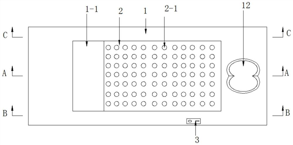
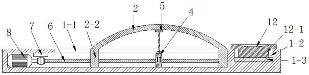
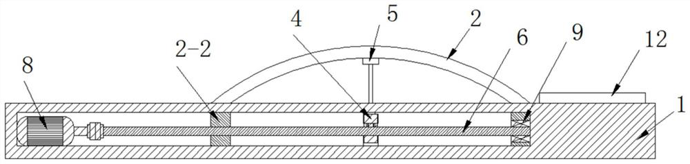
[0027] Such as Figure 1-Figure 8 As shown, this specific embodiment adopts the following technical scheme: it includes base 1, arch plate 2, control switch group 3, electric lifting rod 4, ejector rod 5, screw rod 6, power supply 7, motor 8, bearing 9, guide shaft 10 and a linear bearing 11; the base 1 is a hollow structure, and the top wall of the hollow structure is provided with a slot 1-1, and an arch plate 2 is movable in the slot 1-1, and the arch plate 2 is a metal plate with a certain deformation The upper surface of the arch plate 2 is integrally formed with several convex points 2-1, and the front and rear of the left and right edges of the arch plate 2 are integrally formed with end plates 2-2, which are located in the end plate 2-2 at the left front end A threaded hole 2-3 is provided, a ball bearing installation hole 2-4 is provided in the end plate 2-2 located at the right front end, and a socket 2-5 is provided in the end plate 2-2 located at the rear end of th...

specific Embodiment approach 2

[0036] see Figure 9-Figure 11 The difference between this embodiment and Embodiment 1 is that: the right side wall of the base 1 is movably embedded with a pedal 17, and the left side wall of the pedal 17 is fixed with a pedal rod 18 front and rear, and The pedal rod 18 is movably inserted in the hole provided in the base 1, and the inner end of the pedal rod 18 is connected with the inner wall of the hole by means of a tension spring 19. The rest of the structure and connection relationship are the same as in the first embodiment. The patient sits on the buttocks. After the buttocks are placed on the board 12, slowly lie on the arch board 2, and manually start the control switch group 3 to make the arch board 2 arch. Push out, pedal 17 under the pulling force of extension spring 19, makes the power that reacts on the direction of pedaling out, thereby increases the resistance force of arch plate 2 to patient's waist, simultaneously, pedal 17 can carry out strength training t...


PUM


Abstract

The invention discloses a convenient lumbar vertebra exercising device for neurosurgery, and relates to the technical field of neurosurgery auxiliary equipment. An arch plate is movably arranged in anopen groove, end plates are integrally formed in front and back of the left and right edges of the arch plate, a threaded hole is formed in the end plate located at the front end of the left side, aball bearing mounting hole is formed in the end plate located at the front end of the right side, and inserting holes are formed in the end plates at the rear ends of the left and right sides; the right side wall of the end plate is fixed to the right side wall of the open groove, and the left side wall of the end plate movably abuts against the left side of the open groove; an ejector rod is movably arranged at the bottom of the arch plate in an abutting mode and fixed to an output shaft of an electric lifting rod, and the bottom of the electric lifting rod is fixed to the inner bottom wall of a base; a screw rod is arranged in the base in the front of the electric lifting rod, and one end of the screw rod is screwed into the ball bearing mounting hole through a ball bearing. The device has the advantages of simple structure, easy movement, low investment cost, easy popularization, high exercise efficiency, convenient adjustment and stronger applicability.

Description

technical field [0001] The invention relates to the technical field of neurosurgery auxiliary equipment, in particular to a convenient lumbar spine exercise device for neurosurgery. Background technique [0002] Some people who have been sitting for a long time or working in postures such as bending over for a long time, most of them will have lumbar spine problems, such as lumbar disc herniation, etc., which will seriously compress the nerves and affect daily life. The current neurosurgery lumbar exercise devices are large in size, complex in structure, inconvenient to move, and high in investment cost, resulting in limited investment and patients need to line up to exercise, which seriously affects the efficiency of lumbar exercise for patients. Need a kind of convenient lumbar vertebra exercising device badly now, be used for reducing its cost, increase its purchase quantity, improve its applicability. Contents of the invention [0003] The object of the present invent...

Claims


Application Information

Patent Timeline
IPC IPC(8): A61H1/00A61H1/02
CPCA61H1/00A61H1/0222A61H2001/0233
Inventor 董丹凤王举波
Owner THE FIRST AFFILIATED HOSPITAL OF MEDICAL COLLEGE OF XIAN JIAOTONG UNIV
Why Eureka
Try Eureka