New tire dismounting device

A tire and mounting seat technology, applied in tire installation, tire measurement, tire parts and other directions, can solve the problems of not being able to completely replace, easy to scratch tires, and small tire hook force to remove tire hooks, shortening the length and increasing the rigidity. , Increase the effect of horizontal rotation

Active Publication Date: 2021-08-10
中意泰达(营口)汽车保修设备有限公司
View PDF10 Cites 0 Cited by
  • Summary
  • Abstract
  • Description
  • Claims
  • Application Information

AI Technical Summary

Problems solved by technology

In order to improve the performance of cars, tires are developed towards small aspect ratio (ratio of tire section height to tire height), hard wall tires, which brings difficulties to tire disassembly
The traditional disassembly method cannot meet the development of the automobile industry. It is difficult to pry the hard arm tire with a manual crowbar, and it is easy to damage the tire. There is an urgent need for new tire removal tools and equipment to adapt to the development of tire technology.
The tire removal device of Italy Corgi Company is a typical four-bar linkage mechanism to control the movement trajectory of the tire removal hook. The movement is transmitted through gears. The structure is complex, the force of the hook tire is small, and the tire removal hook is easy to scratch the tire. tire machine upgrade
The tire removal device of Italy Jiuliang Company is a cam groove and a connecting rod to control the movement track of the tire removal hook. The overall device is suitable for upgrading the old tire removal machine, but the cam structure has the disadvantages of low mechanical transmission efficiency and short service life. All these automatic tire removal devices have to dismantle the tire dismounting working head of the original machine. Both kinds of working heads have limitations when dismounting tires and cannot completely replace the traditional working head.
And Italy's BUTLER has also launched a new tire removal mode. It uses a plastic working head with a hook, which has an introduction surface and a surface, inserting it into the tire and then lifting it out. However, the product cannot be installed independently on any machine.

Method used


Image

  • New tire dismounting device
  • New tire dismounting device
  • New tire dismounting device

Examples


Embodiment Construction

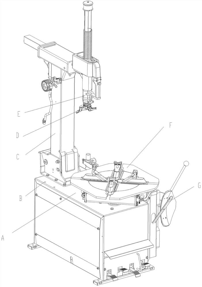
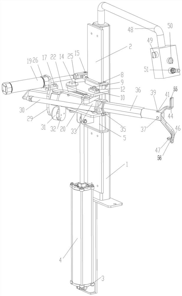
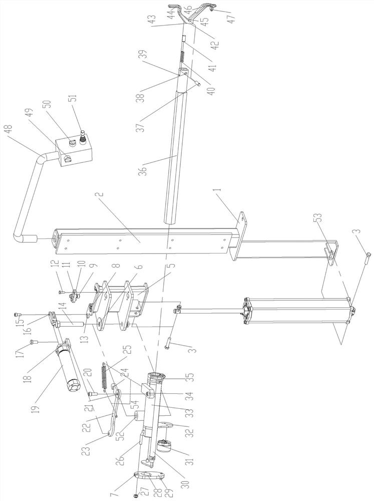
[0040] As shown in the figure, the present invention includes a fixed bracket 1, the upper part of the fixed bracket 1 is provided with a vertical guide rail 2, the lower end of the fixed bracket 1 is hinged to the lower end of the vertical first executive cylinder body, and the vertical guide rail 2 is provided with a sliding support 5, the second The lower end of the hinged sliding support 5 at the power output end of the upper end of the executive cylinder;

[0041] One side of the sliding support 5 is hinged with the rear portion of the horizontal support frame 33, and the horizontal support frame 33 is equipped with a working arm 36, a second actuator cylinder for driving the axial locking of the working arm 36, and a fourth cylinder for driving the axial movement of the working arm 36. Execution cylinder;

[0042] The middle part of the lock hook 22 is hinged on the horizontal support frame 33 , one end of the lock hook 22 is hinged to the main body of the third actuator...


PUM


Abstract

A novel tire disassembly and assembly device belongs to the technical field of tire disassembly and assembly, and in particular relates to a novel tire disassembly and assembly device. The invention provides a novel tire dismounting device with good use effect. The present invention includes a fixed bracket 1, which is characterized in that the upper part of the fixed bracket 1 is provided with a vertical guide rail 2, the lower end of the fixed bracket 1 is hinged to the lower end of the vertical first actuator main body, and the vertical guide rail 2 is provided with a sliding support 5, the first actuator The power output end of the upper end of the cylinder is hinged to the lower end of the sliding support 5; one side of the sliding support 5 is hinged to the rear of the horizontal support frame 33, and the horizontal support frame 33 is equipped with a working arm 36, which drives the second execution of the axial locking of the working arm 36. Cylinder and the fourth executive cylinder that drives the working arm 36 to move axially; the middle part of the lock hook 22 is hinged on the horizontal support frame 33, one end of the lock hook 22 is hinged with the main body of the third executive cylinder 19, and the other end of the lock hook 22 is pivotally connected to the sliding support 5 , the rod end of the third executive cylinder 19 is hinged with the sliding support 5 .

Description

technical field [0001] The invention belongs to the technical field of tire disassembly and assembly, and in particular relates to a novel tire disassembly and assembly device. Background technique [0002] Car tires are usually made of two parts, the rim (metal) and the tire (rubber), with the rim having an annular flange along the perimeter to which the bead of the elastic rubber tire fits. To dismount the tire is to lift the bead of the rubber tire onto the annular flange of the metal rim, thereby separating the tire from the rim (installation is the opposite). The traditional tire dismounting method is to have a tire dismounting machine. The dismounting machine is composed of a box body, a column, a lifting arm, a working head, a rotating chuck, and a manual crowbar. On the disk, the lifting arm drives the working head close to the edge of the rim, and the bead lip of the tire is pried to the leading surface of the working head with a manual crowbar. The tire rotates cl...

Claims


Application Information

Patent Timeline
Patent Type & Authority Patents(China)
IPC IPC(8): B60C23/04
CPCB60C25/0506B60C25/053B60C25/0578
Inventor 仲婧宇侯永杰王妮邴常松陈洪毅
Owner 中意泰达(营口)汽车保修设备有限公司
Why Eureka
Try Eureka