Rotor, motor, rotor locking method and transportation tool

A technology of rotor and rotor shaft, applied in the manufacture of stator/rotor body, magnetic circuit rotating parts, magnetic circuit shape/style/structure, etc., can solve the problems of non-repeatable disassembly, low fault tolerance, and increase of rotor shaft length, etc. , to achieve the effect of safe and reliable locking method, simple locking method and reducing process cost

Active Publication Date: 2019-10-18
GREE ELECTRIC APPLIANCES INC
View PDF5 Cites 0 Cited by
  • Summary
  • Abstract
  • Description
  • Claims
  • Application Information

AI Technical Summary

Problems solved by technology

This process is often complicated to operate and high in cost, and it takes up the internal space of the motor, which will increase the length of the rotor shaft and increase the cost of the motor
Moreover, this process cannot be disassembled and assembled repeatedly, and the fault tolerance rate is very low, and long-term operation will cause the nuts to loosen, make the silicon steel sheets become scattered, increase the noise of the motor, and affect the performance of the motor

Method used


Image

  • Rotor, motor, rotor locking method and transportation tool
  • Rotor, motor, rotor locking method and transportation tool
  • Rotor, motor, rotor locking method and transportation tool

Examples


no. 1 example

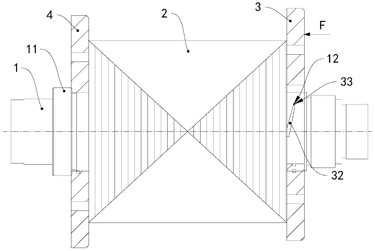
[0041] see figure 1 , the rotor of this embodiment includes a rotor shaft 1 , a rotor core 2 , a baffle 4 , a baffle 3 and a connecting assembly 10 . The rotor core 2, the baffle 3 and the baffle 4 are all sleeved on the rotor shaft 1, and the rotor core 2 is located between the baffle 3 and the baffle 4, and the baffle 4 and the rotor core 2 are on the rotor shaft 1. It is limited axially between the shaft shoulder 11 of the rotor shaft 1 and the baffle 3 , and the baffle 4 abuts against the shaft shoulder 11 in the axial direction.

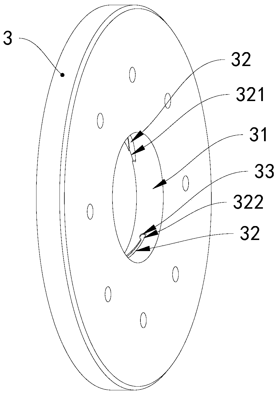
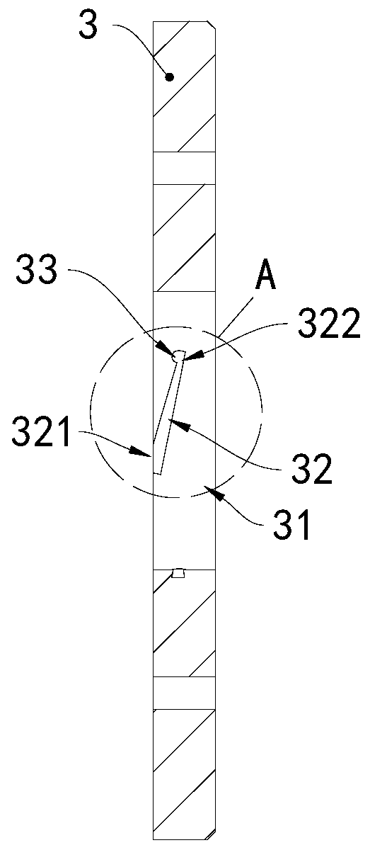
[0042] see Figure 1 to Figure 3 , the baffle plate 4 and the baffle plate 3 are both ring-shaped, and the middle part of the baffle plate 3 is provided with a circular hole 31, the circular hole 31 is in clearance fit with the rotor shaft 1, and the connecting assembly 10 is connected between the circular hole 31 and the rotor shaft 1 Between them, the connecting assembly includes an arc-shaped guiding groove 32 and a cylindrical limiting pro...

no. 4 example

[0067] As the description of the fourth embodiment of the rotor and the rotor locking method of the present invention, only the differences from the third embodiment of the above-mentioned rotor and the rotor locking method will be described below.

[0068] see Figure 13 , the limit groove 72 of this embodiment includes an axial limit portion 721 and a circumferential limit portion 722, the guide groove 71, the axial limit portion 721 and the circumferential limit portion 722 are sequentially connected, and the circumferential limit portion 722 The outlet end 723 of the axial limiting portion 721 extends along the axial direction of the rotor to a side close to the stator core.

[0069] In the steps of the rotor locking method, after the stop protrusion 70 enters the axial limit portion 721 of the limit groove 72 from the outlet 712 of the guide groove 71, the baffle plate 7 continues to be rotated, and the limit protrusion 70 is limited from the axial direction. The outlet ...


PUM


Abstract

The invention provides a rotor, a motor, a locking method of the rotor and a transportation tool. The rotor comprises a rotor shaft, a rotor core and a baffle plate, wherein the rotor core and the baffle plate are both sleeved on the rotor shaft, and the rotor core is limited between a shaft shoulder of the rotor shaft and the baffle plate in the axial direction of the rotor shaft. A circular holeis formed in the baffle plate in a penetrating mode and is in clearance fit with the rotor shaft. The rotor also comprises a connecting assembly, and the connecting assembly is connected between thecircular hole and the rotor shaft. The connecting assembly comprises a guide groove and a limiting protrusion, and the limiting protrusion can move in the extending direction of the guide groove. Theguide groove comprises an inlet and an outlet, wherein the outlet is provided with a limiting groove communicated with the guide groove, the projection of the limiting groove on the axis of the rotorand the projection of the inlet on the axis of the rotor are arranged at intervals, and the limiting groove limits the displacement of the limiting protrusion in the axial direction of the rotor. Therotor is simple in assembly process, large in locking force and detachable.

Description

technical field [0001] The invention relates to the technical field of motors, in particular to a rotor, a motor, a locking method for the rotor and a transportation tool. Background technique [0002] Nowadays, motors have been applied to all aspects of life and become an indispensable part of life. It is widely used in automobiles, motorcycles, electric bicycles, battery vehicles, ships, aviation, machinery and other industries, and is also widely used in some high-end products. More than billions of motors are produced every year, and there are countless manufacturers of motors. The structure of the motor mainly includes a stator, a rotor, a rotor shaft, a casing, and front and rear end covers. The stator is in interference fit with the casing, and the rotor is fixed on the rotor shaft. [0003] At present, most motors use baffles to cooperate with the rotor core to ensure the overlapping coefficient of the rotor core and limit the axial displacement of the magnetic st...

Claims


Application Information

Patent Timeline
Patent Type & Authority Applications(China)
IPC IPC(8): H02K1/28H02K15/02
CPCH02K1/28H02K15/02
Inventor 谭福慧唐志伟杨晓琴董垚高尤坤张静
Owner GREE ELECTRIC APPLIANCES INC
Why Eureka
Try Eureka