Multi-rotor unmanned aerial vehicle lifting rack

A multi-rotor unmanned aerial vehicle technology, applied in the field of aerial vehicles, can solve the problems of high price, complex design of unmanned aerial vehicles, no manned manned, etc., and achieves the effects of low cost, improved energy utilization, and convenient setting.

Pending Publication Date: 2021-02-02
叶殊钨
View PDF0 Cites 0 Cited by
  • Summary
  • Abstract
  • Description
  • Claims
  • Application Information

AI Technical Summary

Problems solved by technology

[0002] Looking at the world, the unmanned aerial vehicles developed at home and abroad are flourishing, and the unmanned aerial vehicles suitable for carrying people and cargo generally have the following problems: 1. Due to the structural limitations of the existing unmanned aerial vehicle frames and arms, The cargo of the existing cargo-carrying unmanned aerial vehicle is generally hoisted under the unmanned aerial vehicle frame, there is a design that is directly exposed and hoisted under the unmanned aerial vehicle frame, and there is also a closed box designed under the unmanned aerial vehicle frame. The design for loading goods, and the design of binding the goods on or below the frame of the unmanned aerial vehicle, and the existing manned unmanned aerial vehicles have not broken the structural limitations of the existing unmanned aerial vehicle frames and arms; There is no ring-shaped cabin bracket in the middle of the frame of the existing unmanned aerial vehicle, and there is no position for the manned (cargo) cabin; three, the outside of the rotor of the existing unmanned aerial vehicle is generally not provided with a shroud. There are unmanned aerial vehicles that are complex in design and expensive

Method used


Image

  • Multi-rotor unmanned aerial vehicle lifting rack
  • Multi-rotor unmanned aerial vehicle lifting rack
  • Multi-rotor unmanned aerial vehicle lifting rack

Examples


Embodiment 1

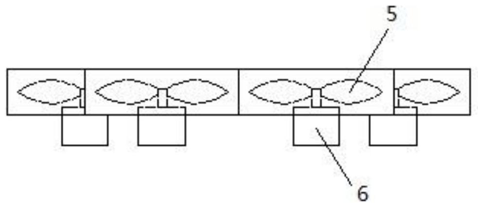
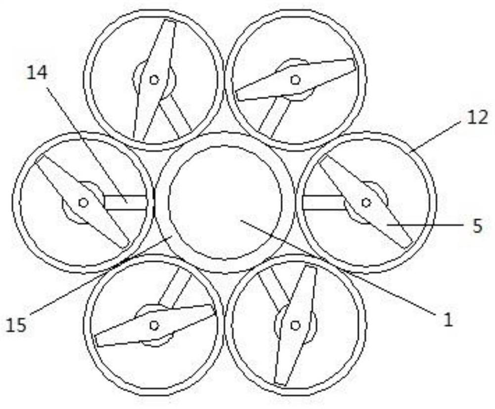
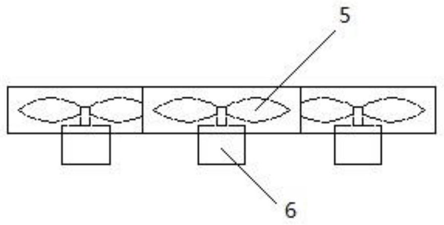
[0036] Such as figure 1 , figure 2 and image 3 As shown, a multi-rotor UAV lifting frame includes a cabin bracket 15, a lifting rotor 5, a power device 6, a support arm 14 and a nozzle cover 12;

[0037] The middle of the cabin bracket 15 is the position 1 where the manned (cargo) cabin is set, and the lift rotors 5 are provided with six, which are arranged in parallel and distributed around the cabin bracket 15 in the circumferential direction, each The lower ends of the lifting rotors 5 are respectively provided with power equipment 6 that drives the operation of the lifting rotors 5, and the power equipment 6 is fixed on the corresponding outer wall of the cabin bracket 15 through a support arm 14. A spinner cover 12 is arranged vertically outside the rotor 5 .

[0038] Specifically, the middle of the cabin bracket 15 is the position 1 where a manned (cargo) cabin is arranged, and the cabin bracket 15 is a circular annular planar structure.

[0039] Specifically, the ...

Embodiment 2

[0042] Such as Figure 4 , Figure 5 and Figure 6 Shown, the difference with embodiment 1 is:

[0043] The middle of the cabin bracket 15 is the position 1 where the manned (cargo) cabin is set, and ten lift rotors 5 are provided.

[0044] Specifically, the middle of the cabin bracket 15 is the position 1 where a manned (cargo) cabin is arranged, and the cabin bracket 15 is an oval annular plane structure.

[0045] Specifically, the power equipment 6 all adopts an engine, and the power source is fuel oil.

Embodiment 3

[0047] Such as Figure 7 , Figure 8 and Figure 9 Shown, the difference with embodiment 1 is:

[0048] The middle of the cabin bracket 15 is the position 1 where the manned (cargo) cabin is set, and the lifting rotors 5 are provided with sixteen.

[0049] Specifically, the middle of the cabin bracket 15 is the position 1 where a manned (cargo) cabin is arranged, and the cabin bracket 15 is a square ring-shaped plane structure.

[0050] Specifically, the power equipment 6 all adopts an engine, and the power source is fuel oil.

[0051] The working principle of embodiment 1, embodiment 2 and embodiment 3:

[0052] The lifting frame of the multi-rotor unmanned aerial vehicle of the present invention is consistent with the working principle of the frame of the existing unmanned aerial vehicle. Because the cabin bracket is arranged in the middle of the lifting frame of the aircraft of the present invention, the control equipment and the power source of the aircraft of the pre...


PUM


Abstract

The invention discloses a multi-rotor unmanned aerial vehicle lifting rack. The multi-rotor unmanned aerial vehicle lifting rack comprises a cabin bracket, lifting rotors, power equipment, supportingarms and a guide cylinder cover. The middle of the cabin bracket is a position where a manned (cargo-carrying) cabin is arranged, the plurality of lifting rotors are circumferentially distributed at the periphery of the cabin bracket in parallel, and the lower end of each lifting rotor is respectively provided with power equipment for driving the lifting rotor to operate. The power equipment is fixed to the outer wall corresponding to the cabin bracket through a supporting arm, and a guide cylinder cover is vertically arranged outside the lifting rotors. Compared with an existing unmanned aerial vehicle rack, the structural limitation of the existing unmanned aerial vehicle rack and vehicle arms is broken through, so that the manned (cargo-carrying) cabin can be arranged in the middle of the unmanned aerial vehicle lifting rack, and the unmanned aerial vehicle lifting rack has the advantages of convenience in manned (cargo-carrying), high energy conversion rate, simple structure, economy and high practicability; the multi-rotor unmanned aerial vehicle lifting rack is the development direction of multi-rotor manned (cargo-carrying) aircrafts in the future.

Description

technical field [0001] The invention relates to the technical field of aircraft, in particular to a lifting frame of a multi-rotor unmanned aerial vehicle. Background technique [0002] Looking at the world, the unmanned aerial vehicles developed at home and abroad are flourishing, and the unmanned aerial vehicles suitable for carrying people and cargo generally have the following problems: 1. Due to the structural limitations of the existing unmanned aerial vehicle frames and arms, The cargo of the existing cargo-carrying unmanned aerial vehicle is generally hoisted under the unmanned aerial vehicle frame, there is a design that is directly exposed and hoisted under the unmanned aerial vehicle frame, and there is also a closed box designed under the unmanned aerial vehicle frame. The design for loading goods, and the design of binding the goods on or below the frame of the unmanned aerial vehicle, and the existing manned unmanned aerial vehicles have not broken the structur...

Claims


Application Information

Patent Timeline
Patent Type & Authority Applications(China)
IPC IPC(8): B64C27/20B64C39/02B64D9/00
CPCB64C27/20B64C39/02B64D9/00B64U50/11B64U10/13B64U50/19B64U30/20B64U2101/60
Inventor 叶殊钨
Owner 叶殊钨
Why Eureka
Try Eureka