Combined heat and power generation system and working method thereof

A technology of combined heat and power generation and hot water, applied in heating systems, hot water central heating systems, heating methods, etc., can solve the contradiction between electrical load regulation and thermal load regulation, limit the deep peak-shaving capacity of heating units, and curtail wind High efficiency and light abandonment rate, etc., to achieve the effect of flexible thermoelectricity, deep peak shaving, and stable load

Active Publication Date: 2021-02-02
STATE POWER INVESTMENT CORP RES INST +1
View PDF8 Cites 4 Cited by
  • Summary
  • Abstract
  • Description
  • Claims
  • Application Information

AI Technical Summary

Problems solved by technology

This is caused by several reasons: first, the economic growth rate in most regions of the Northeast and Northwest is slow, and the growth of electricity consumption is also relatively slow; second, the northern region is rich in wind power, photovoltaic and other renewable energy The capacity is increasing rapidly; thirdly, at present, most of the heating power plant units are extraction steam units with condensers, and the power supply is mainly used in the non-heating season, and it needs to undertake the heating task in the heating season. The units all adopt steam turbine medium-pressure cylinder exhaust steam heat supply mode, but limited by the minimum cooling flow rate of the steam turbine low-pressure cylinder, under the condition of a certain heat supply of the unit, the power generation load of the unit cannot be lower than a certain limit value, in order to ensure heat supply, Need to operate at a higher load rate, this mode of "heating fixed power" limits the deep peak-shaving ability of the heating unit during the heating period
These three factors have reduced the power load regulation capacity of cogeneration units in the Northeast and Northwest regions during the heating season, resulting in the contradiction between electric load regulation and heat load regulation, and difficulty in peak regulation, which also makes the curtailment rate of wind and light curtailment. stay high

Method used


Image

  • Combined heat and power generation system and working method thereof
  • Combined heat and power generation system and working method thereof

Examples


Embodiment Construction

[0030] Embodiments of the invention are described in detail below, examples of which are illustrated in the accompanying drawings. The embodiments described below by referring to the figures are exemplary and are intended to explain the present invention and should not be construed as limiting the present invention.

[0031] Refer below figure 1 with figure 2 A combined heat and power system according to an embodiment of the present invention will be described.

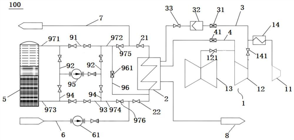
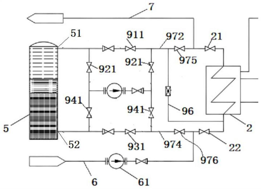
[0032] Such as figure 1 with figure 2 As shown, the combined heat and power system 100 according to the embodiment of the present invention includes a turbo-generator unit 1, a heat network heater 2, a low-pressure bypass 3, a steam extraction pipeline 4, a hot water container, a heat supply and return water pipeline 6 and a supply Hot water supply pipeline 7.

[0033] The turbogenerator set includes a high-pressure cylinder 11, a medium-pressure cylinder 12, a low-pressure cylinder 13 and a reheater 14. The st...


PUM


Abstract

The embodiment of the invention provides a combined heat and power generation system. The combined heat and power generation system comprises a steam turbine generator unit, a heat supply network heater, a low-pressure bypass, a steam extraction pipeline, a hot water container, a heat supply and water return pipeline, and a heat supply and water supply pipeline; the first end of the low-pressure bypass communicates with a steam outlet of a reheater, and the second end of the low-pressure bypass communicates with a steam inlet of the heat supply network heater; the first end of the steam extraction pipeline communicates with a steam outlet of a medium-pressure cylinder, and the second end of the steam extraction pipeline communicates with a steam inlet of the heat supply network heater; thehot water container is provided with a hot water inlet and a hot water outlet, and the hot water inlet communicates with a hot water outlet of the heat supply network heater; the heat supply and water return pipeline communicates with a cold water inlet of the heat supply network heater; and the heat supply and water supply pipeline communicates with a hot water outlet of the heat supply networkheater and a hot water outlet of the hot water container. The combined heat and power generation system provided by the embodiment of the invention has the advantages of flexible adjustment of heat and power, large peak shaving depth, good economic benefit, stable load and the like.

Description

technical field [0001] The invention relates to the technical field of power generation and heat supply cogeneration, in particular to a heat and power cogeneration system and a working method thereof. Background technique [0002] In recent years, my country's wind power, photovoltaic and other renewable energy sources have developed rapidly, and the installed capacity has increased rapidly. During the heating season in the northern regions of my country, especially the northeast and northwest regions, due to the overcapacity of electricity, the problems of renewable energy consumption and power grid peak regulation are very prominent. This is caused by several reasons: first, the economic growth rate in most regions of the Northeast and Northwest is slow, and the growth of electricity consumption is also relatively slow; second, the northern region is rich in wind power, photovoltaic and other renewable energy The capacity is increasing rapidly; thirdly, at present, most ...

Claims


Application Information

Patent Timeline
Patent Type & Authority Applications(China)
IPC IPC(8): F01K17/06F24D3/10
CPCF01K17/06F24D3/1058Y02E20/14
Inventor 张国强卢华白宁王为民郑远凯范瑞君王刚张谨奕张玮郭霄宇
Owner STATE POWER INVESTMENT CORP RES INST
Why Eureka
Try Eureka