Supercharge Your Innovation With Domain-Expert AI Agents!

Positioning method for determining measurement points of acceleration sensors of head-type impact module

A technology of acceleration sensor and positioning method, which is applied in the direction of impact test, measuring device, machine/structural component test, etc. It can solve the problems of uncertain force direction, small size, and large test result, etc., and achieve the effect of improving accuracy

Active Publication Date: 2021-02-02
CHONGQING CHANGAN AUTOMOBILE CO LTD
View PDF16 Cites 0 Cited by
  • Summary
  • Abstract
  • Description
  • Claims
  • Application Information

AI Technical Summary

Problems solved by technology

However, for a spherical impactor such as a head-shaped impact module, the direction of the force is not fixed, and it is not perpendicular to the installation surface of the acceleration sensor. The position of the measurement point of the acceleration sensor will directly affect the test results.
[0003] For different brands and models of acceleration sensors, because the distance between the position of the sensitive element and the installation hole of the acceleration sensor is different, the measurement points of different brands and models of acceleration sensors may be different under the same installation position of the installation platform. This will directly affect the accuracy of the test results, resulting in larger or smaller test results

Method used


Image

  • Positioning method for determining measurement points of acceleration sensors of head-type impact module
  • Positioning method for determining measurement points of acceleration sensors of head-type impact module
  • Positioning method for determining measurement points of acceleration sensors of head-type impact module

Examples


Embodiment Construction

[0023] The present invention will be described in detail below in conjunction with the accompanying drawings.

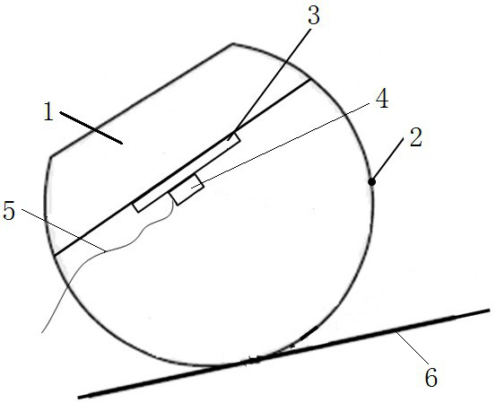
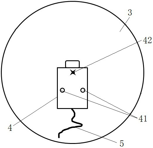
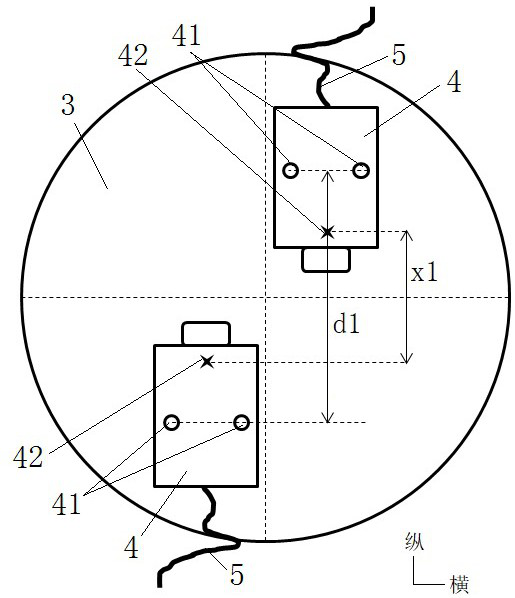
[0024] see figure 1 , the head-shaped impact module shown includes a cover plate 1 and a hemispherical head-shaped model part 2, the cover plate 1 closes the opening of the head-shaped model part 2 to form a cavity, and the cover plate 1 is close to the middle of one side of the cavity Convex is provided with the installation platform 3 that is cylindrical, see figure 2 , the acceleration sensor 4 is fixed on the installation platform 3 through the installation hole 41, and the measurement point 42 of the acceleration sensor 4 is located on the center line of the installation platform 3, while ensuring that the measurement point 42 coincides with the center of the sphere of the head model part 2, it needs to be explained Yes, since the installation platform 3 is a cylinder, its center line is the line connecting the centers of the upper and lower circles. The outp...


PUM


Abstract

The invention discloses a positioning method for determining measurement points of acceleration sensors of a head-shaped impact module, and the method comprises the following steps: S1, fixing two acceleration sensors with the same model on an installation platform, carrying out the first pedestrian protection head-shaped impact test, and recording an output acceleration peak value; S2, adjustingthe relative position between the two acceleration sensors in the longitudinal direction of the installation platform, conducting a second pedestrian protection head shape impact test , and recordingan output acceleration peak value; S3, determining the distance between the measuring points on the acceleration sensors and the connecting line of the mounting holes, adjusting the positions of the two acceleration sensors, then carrying out a pedestrian protection head shape impact test, and recording output acceleration peak values A13 and A23; if A13 is equal to A23, indicating that the measurement point is successfully positioned, and if A13 is not equal to A23, repeating S1 and S2. The influence of acceleration sensors of different brands and models on the impact test result of the headtype impact module can be eliminated, and the accuracy of test data is improved.

Description

technical field [0001] The invention relates to a head-shaped impact test for pedestrian protection, in particular to a positioning method for determining a measurement point of an acceleration sensor of a head-shaped impact module. Background technique [0002] Pedestrian protection regulations and evaluation rules require that the acceleration sensor be installed at the center of mass of the head-shaped impact module, that is, the geometric center. Usually, the acceleration sensor is fixed to the head impact module through the installation platform, that is, the installation position of the acceleration sensor is fixed. When the acceleration sensor is working, the test direction is perpendicular to the installation surface. For the case where the force direction of the tested sample is perpendicular to the acceleration sensor installation surface, the position change of the acceleration sensor in the installation plane does not affect the test results. However, for a sphe...

Claims


Application Information

Patent Timeline
IPC IPC(8): G01M7/08
CPCG01M7/08
Inventor 刘文举赵会李筱磊涂超吴旗浩
Owner CHONGQING CHANGAN AUTOMOBILE CO LTD
Features
  • R&D
  • Intellectual Property
  • Life Sciences
  • Materials
  • Tech Scout
  • Unparalleled Data Quality
  • Higher Quality Content
  • 60% Fewer Hallucinations
Learn More