
Damping industrial microwave device with fixed clamping structure

An industrial microwave and fixed clamping technology, which is applied in microwave heating and other directions, can solve the problems of no shock-absorbing structure, no fixed structure, material displacement in equipment, etc., and achieve the effect of simple use, convenient handling, and solution to shaking

Active Publication Date: 2021-02-02
娄底光华机械设备制造有限公司
View PDF2 Cites 1 Cited by
  • Summary
  • Abstract
  • Description
  • Claims
  • Application Information

AI Technical Summary

Problems solved by technology

[0004] The object of the present invention is to provide a shock-absorbing industrial microwave device with a fixed clamping structure to solve the problem that the existing station microwave equipment proposed in the above-mentioned background technology does not have a shock-absorbing structure. , it may be caused by the shaking of the fuselage, and in addition, there is no fixed structure inside the microwave equipment of many stations, which will cause the displacement of the material inside the equipment and affect the processing effect.

Method used


Image

  • Damping industrial microwave device with fixed clamping structure
  • Damping industrial microwave device with fixed clamping structure
  • Damping industrial microwave device with fixed clamping structure

Examples


Embodiment Construction

[0026] The following will clearly and completely describe the technical solutions in the embodiments of the present invention with reference to the accompanying drawings in the embodiments of the present invention. Obviously, the described embodiments are only some, not all, embodiments of the present invention. Based on the embodiments of the present invention, all other embodiments obtained by persons of ordinary skill in the art without making creative efforts belong to the protection scope of the present invention.

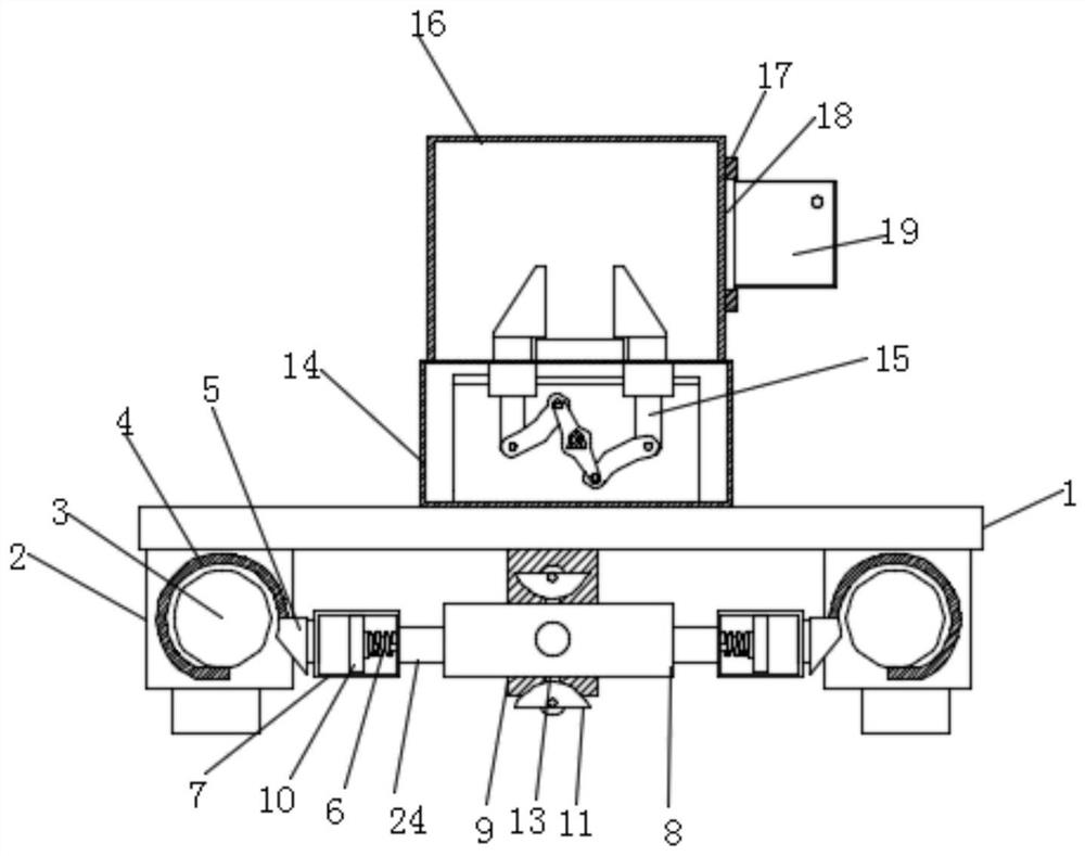
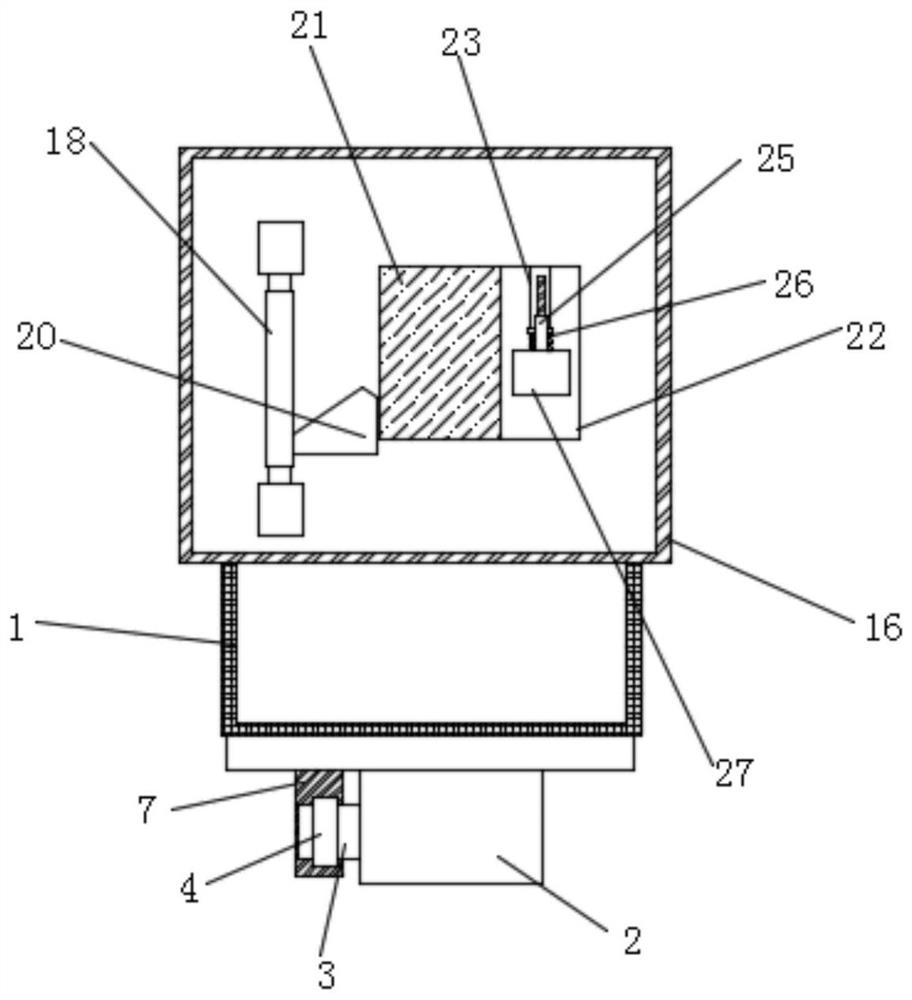
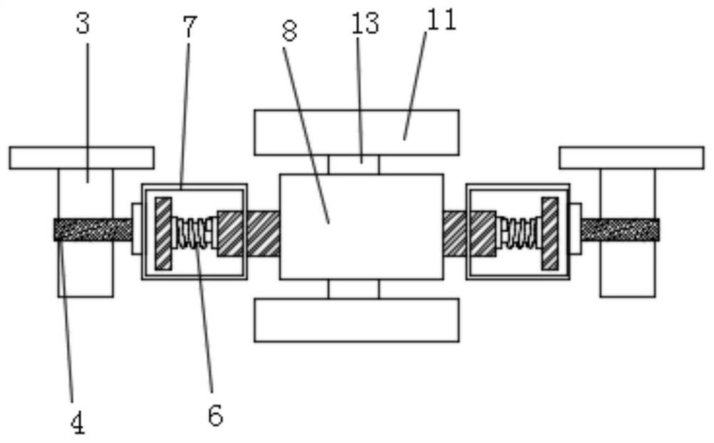
[0027] see Figure 1~6, in an embodiment of the present invention, a shock-absorbing industrial microwave device with a fixed clamping structure includes a support plate 1, the bottom of the support plate 1 is fixedly connected with a support frame 2, and one end of the support frame 2 is fixedly connected with a second One connecting rod 3, the surface of the first connecting rod 3 is sleeved with a collar 4, and the collar 4 surrounds the first connecting ro...


PUM


Abstract

The invention discloses a damping industrial microwave device with a fixed clamping structure. The device comprises a supporting plate, wherein a supporting frame is fixedly connected to the bottom ofthe supporting plate, a first connecting rod is fixedly connected to one end of the supporting frame, the surface of the first connecting rod is sleeved with a sleeve ring, a first transmission rod is welded to the side face of the sleeve ring, the surface of the first transmission rod is fixedly connected with a limiting frame, the side face of the limiting frame is movably connected with a second transmission rod, the left side of the second transmission rod is fixedly connected with a first spring, the side face of the first spring is fixedly connected with a limiting ring, and the right side of the second transmission rod is rotationally connected with a clamping rod. According to the invention, a motor drives a transmission block to rotate, when the transmission block rotates, a first driven block and a second driven block are driven to form a reverse rotation structure, and then the first driven block and the second driven block drive two sets of sliding blocks to slide throughtwo sets of transmission rods, so that the purpose of clamping and fixing materials through the clamping blocks is achieved.

Description

technical field [0001] The invention relates to the field of industrial microwaves, in particular to a shock-absorbing industrial microwave device with a fixed clamping structure. Background technique [0002] Industrial microwave equipment is a kind of equipment that many factories often use when processing workpieces. Microwave is an electric wave with a frequency of 300 MHz to 300 GHz. The water molecules in the heated medium material are polar molecules. Under the action of a rapidly changing high-frequency electromagnetic field, its polar orientation will change with the change of the external electric field. Molecular movement shows mutual friction effect. At this time, the field energy of the microwave field is converted into heat energy in the medium, which raises the temperature of the material, produces a series of physical and chemical processes such as thermalization and puffing, and achieves the purpose of microwave heating and drying. Industrial microwave equip...

Claims


Application Information

Patent Timeline
IPC IPC(8): H05B6/64
CPCH05B6/64
Inventor 谢平光
Owner 娄底光华机械设备制造有限公司
Learn More