
A vacuum pumping method and vacuum pumping device for a low-temperature tank car

A technology of vacuuming device and low temperature tank, which is applied in the field of vacuuming, can solve the problems of long vacuuming time, high cost of returning vehicles to the factory, and inability to stop at will, so as to reduce the vacuuming time and reduce the long vacuuming time. , The effect of easy positioning and maintenance

Active Publication Date: 2021-05-18
湖南省特种设备检验检测研究院
View PDF7 Cites 0 Cited by
  • Summary
  • Abstract
  • Description
  • Claims
  • Application Information

AI Technical Summary

Problems solved by technology

[0003] At present, when the vacuum degree is found to be unqualified, except for a few large-scale inspection agencies and users who have vacuum equipment, a third party is required to provide vacuum service. Usually, the vehicle is returned to the factory for vacuum extraction, and the cost of returning the vehicle to the factory is expensive. It takes a lot of time
[0004] Even if the unit has vacuum extraction equipment, because of the volume of the tank and the need for a high vacuum environment, the extraction of high vacuum has very high requirements for the extraction equipment, and the extraction process takes a long time and consumes a lot of energy.
[0005] In the process of vacuuming, if there is a leak between the equipment, it will also affect the time of vacuuming, especially when pumping high vacuum. When vacuuming, the vacuum interlayer in the low-temperature tanker will absorb the outside air, and the inhaled air contains a lot of moisture, which will make the next vacuuming time longer

Method used


Image

  • A vacuum pumping method and vacuum pumping device for a low-temperature tank car
  • A vacuum pumping method and vacuum pumping device for a low-temperature tank car
  • A vacuum pumping method and vacuum pumping device for a low-temperature tank car

Examples


Embodiment Construction

[0041] In order to enable those skilled in the art to better understand the technical solution of the present invention, the present invention will be described in detail below in conjunction with the accompanying drawings. The description in this part is only exemplary and explanatory, and should not have any limiting effect on the protection scope of the present invention. .

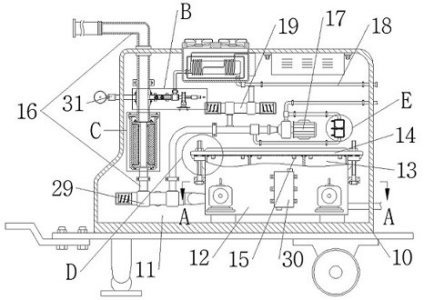
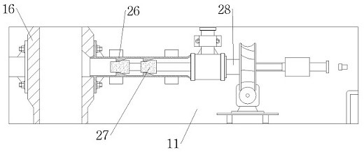
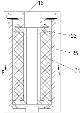
[0042] As attached to the manual Figure 1-8 As shown, the specific structure of the present invention is: a vacuum pumping method for a low-temperature tank car and a vacuum pumping device, including an outer box body 10, an inner cavity 11 is arranged in the outer box body 10, and a sealed box is fixedly arranged in the inner cavity 11 Body 12, the suction pipe mouth provided in the sealed box 12 is connected to the main pipeline 16, a number of compartments 13 are arranged in the sealed box 12, and six compartments 13 are specifically arranged, and the sealed box 12 is fixedly connected with a cont...


PUM


Abstract

The invention discloses a vacuum pumping method and a vacuum pumping device for a low-temperature tank car, which belong to the field of vacuum pumping, and include an outer box body, an inner cavity is arranged in the outer box body, a sealed box body is fixedly arranged in the inner cavity, and a sealed box body is fixed in the sealed box body. The mouth of the suction pipe set in the body is connected to the main pipe, and several compartments are set in the sealed box, and the side of the sealed box is fixedly connected to the controller, which is convenient for quick positioning and maintenance, and the sealed compartments can reduce the The problem of long vacuuming time caused by air tightness, by setting up a backup suction pump, can continue to vacuumize the inside of the tank when the main components of vacuuming cannot work and be used normally. When the pressure of the suction port is lower than the pressure of the discharge port, the air intake control valve is controlled to open, and the replacement gas is filled into the tank body, which can greatly reduce the water vapor entering the vacuum interlayer of the tank body.

Description

technical field [0001] The invention belongs to the field of vacuuming, in particular to a vacuuming method and a vacuuming device for a low-temperature tank car. Background technique [0002] Cryogenic tank trucks mainly transport low-temperature media such as liquid nitrogen, liquid oxygen, liquid argon, and LNG. With the rapid development of society and economy, the demand for low-temperature transportation media is increasing. The low-temperature media should be kept as liquid as possible during transportation. One is to prevent the pressure rise caused by vaporization, and the other is to safely discharge the pressure rise after vaporization, resulting in a waste of energy resources. In order to maintain the liquid state of the low-temperature medium, it is necessary to do a good job of heat insulation for the tank body, and use the interlayer to set up a vacuum layer It is the best way at present, and the vacuum degree detection of the vacuum layer is one of the key in...

Claims


Application Information

Patent Timeline
Patent Type & Authority Patents(China)
IPC IPC(8): F04B41/06F04B37/14F16K1/44F04B39/00
CPCF04B37/14F04B39/00F04B41/06F16K1/44F17C2203/0391
Inventor 罗更生陈湘清詹建荣罗翔艾青锋黄雪优罗金
Owner 湖南省特种设备检验检测研究院
Learn More