Chemical process pump with adjustable bearing gland

A bearing gland and process pump technology, which is applied to the components, pumps, and pump components of the pumping device for elastic fluid, can solve the problem of increasing the radial runout value of the bearing, extruding the bearing diameter, and changing the length, etc. problems, to achieve the effect of smooth adjustment, improved bearing adaptation, and improved stability

Active Publication Date: 2021-02-05
ZHEJIANG OCEAN UNIV
View PDF6 Cites 0 Cited by
  • Summary
  • Abstract
  • Description
  • Claims
  • Application Information

AI Technical Summary

Problems solved by technology

[0003] Regardless of the process pump used in any occasion, it needs to be used in conjunction with the bearing to exert its driving ability. However, the current bearings are large and small, wide and narrow, with various types and different working conditions. Under the environment, the bearing will also undergo a series of shape changes with the change of the environmen

Method used


Image

  • Chemical process pump with adjustable bearing gland
  • Chemical process pump with adjustable bearing gland
  • Chemical process pump with adjustable bearing gland

Examples


Embodiment 1

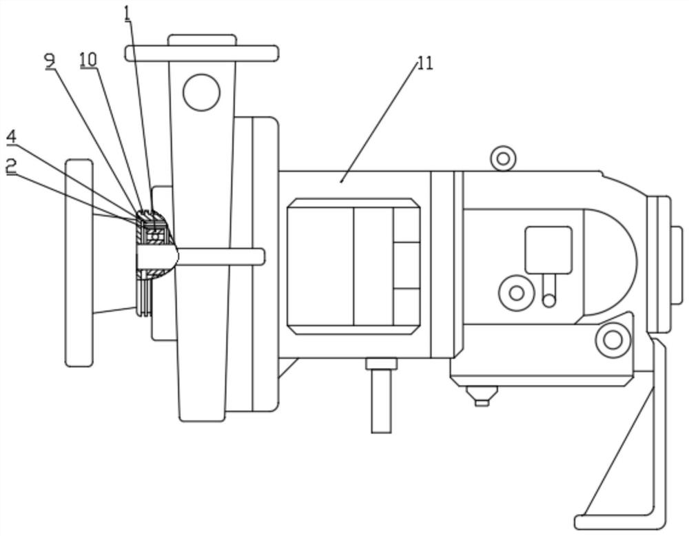
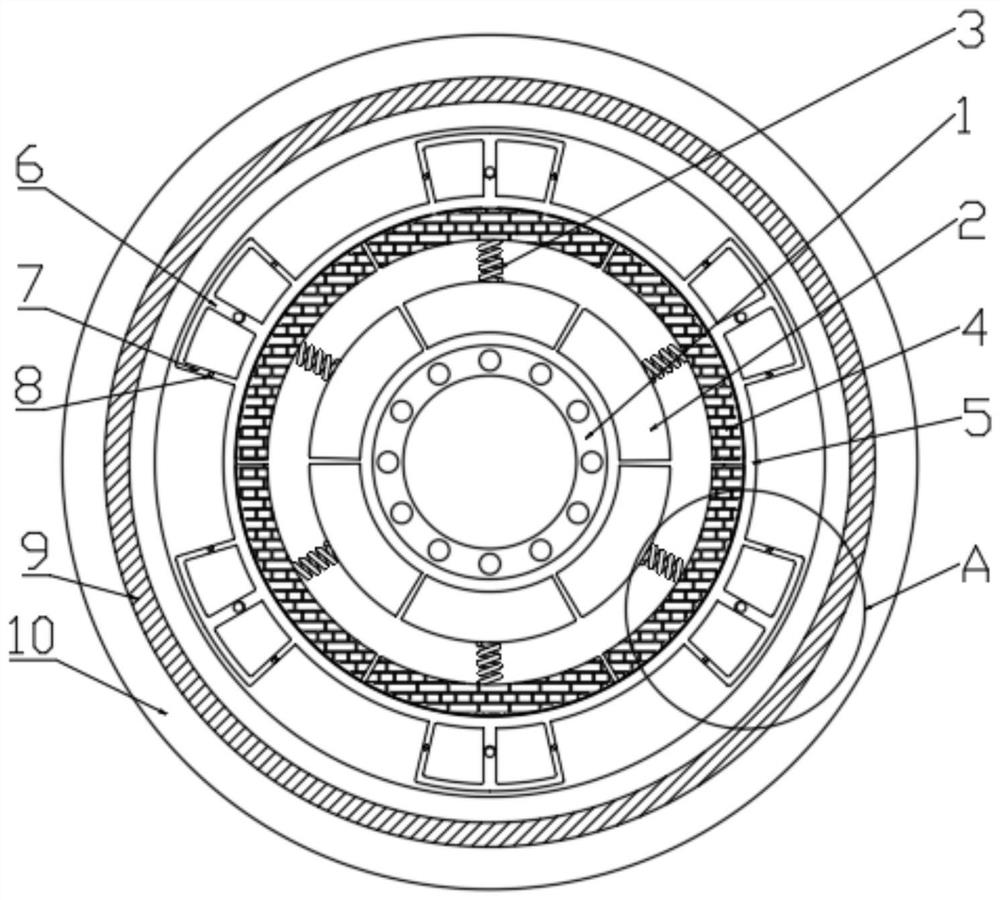
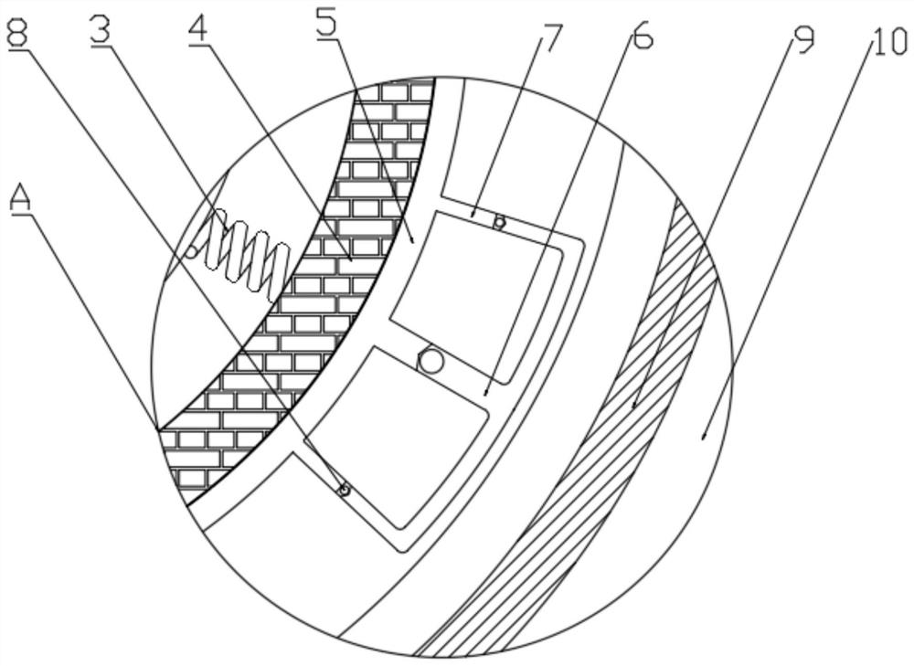
[0024] see Figure 1-6 , a chemical process pump with an adjustable bearing gland, comprising a process pump body 11, a bearing gland 9 and a bearing 1, a bearing 1 is installed in the process pump body 11 through the bearing gland 9, and the bearing 1 is set In the bearing gland 9, a first buffer layer and a second buffer layer are arranged between the bearing 1 and the bearing gland 9, and the first buffer layer and the second buffer layer are arranged along the radial direction of the bearing 1. Arranged sequentially from the inside to the outside; the second buffer layer includes an air flow pipe 5, a main flow channel 6 and a side flow channel 7, the air flow pipe 5 is arranged on the periphery of the first buffer layer, and the air flow pipe 5 is also communicated with A plurality of main channels 6, the side of the main channel 6 is also provided with a side channel 7, and the two ends of the side channel 7 are respectively connected with the main channel 6 and the air ...

Embodiment 2

[0029] In order to further improve the practicability of this design, improvements have been added on the basis of Embodiment 1, the improvements are: please refer to Figure 1-6 , the first buffer layer includes a first movable block 2 and a second movable block 4, the number of the first movable block 2 and the second movable block 4 is multiple, and each first movable block 2 is elastically The connecting piece is connected with the second movable block 4 corresponding to the first movable block 2; the airflow pipe 5 is fitted on the outside of the second movable block 4; the first movable block 2 is fitted on the bearing 1 outside.

[0030] The elastic connector is the first spring 3 .

[0031] The setting of the first buffer layer can improve the resistance of the design to the radial runout of the bearing;

[0032] Specifically, when the bearing runs offset, it will first squeeze the first movable block 2, and then through the elastic action of the first spring 3, part...


PUM


Abstract

The invention discloses a chemical process pump with an adjustable bearing gland. The pump comprises a process pump body, the bearing gland and a bearing, a second buffer layer comprises an air flow pipe, main flow channels and side flow channels, the air flow pipe is further communicated with the plurality of main flow channels, and the side flow channels are further arranged on the side surfacesof the main flow channels. The two ends of each side flow channel are communicated with the corresponding main flow channel and the air flow pipe respectively, and one-way valves are further arrangedin the main flow channels and the side flow channels; and the air flow pipe is provided with the plurality of main flow channels and side flow channels, so that when the main flow channel at a certain position is extruded by the deviation motion of the bearing, gas in the air flow pipe can flow, the gas flowing out of the side flow channels at the two sides of each main flow channel has radial runout resistance, gas flowing out of the side flow channels located at other positions also has certain bearing deviation resistance, so that rotation of the bearing can be adjusted more gently throughthe design, and the operation stability of the process pump is improved.

Description

technical field [0001] The invention relates to the field of chemical process pump assembly, in particular to a chemical process pump with an adjustable bearing cover. Background technique [0002] Chemical process pump is the general term for various pumps in the chemical production process. In chemical or petrochemical production, pumps work under high temperature, low temperature or ultra-low temperature, high pressure, flammable, explosive, toxic and other strong corrosive media. [0003] Regardless of the process pump used in any occasion, it needs to be used in conjunction with the bearing to exert its driving ability. However, the current bearings are large and small, wide and narrow, with various types and different working conditions. Under the environment, the bearing will also undergo a series of shape changes with the change of the environment. For example, under high temperature, the oil in the bearing will expand irregularly and squeeze the inner and outer rin...

Claims


Application Information

Patent Timeline
IPC IPC(8): F04D29/046F04D29/40F04D29/66
CPCF04D29/046F04D29/406F04D29/669
Inventor 徐佳乐林佳胡家希
Owner ZHEJIANG OCEAN UNIV
Why Eureka
Try Eureka